27
4.4 Checking the pressure reducer
4.4.1 Checking the pressure reducer for the stroke drive
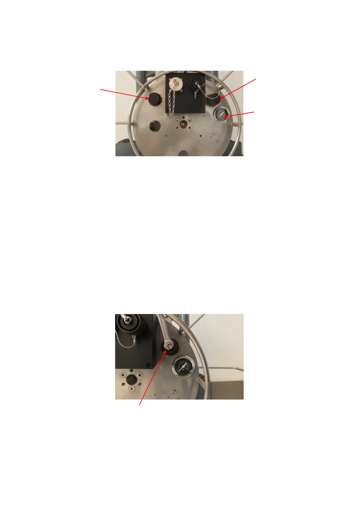
The stroke pressure is indicated by a pressure gauge. Actuate to full stroke and read the
pressure in the pressure gauge. The adjusted pressure must be 6 bar.
Otherwise pry the cap off the pressure reducer 1 (DM1) with a screwdriver and keep turning
the nut on the pressure reducer with an NW 6 open end spanner, until the pressure gauge
indicates a pressure of 6 bar Turning clockwise increases the pressure. Turning counter-
clockwise reduces the pressure.
Once the pressure is correctly adjusted, check the setting several times. Actuate and relieve
several times.
Seal the adjusting screw, place the cap on the pressure reducer 1 and press it on to snap
into place.
If an adjustment is not possible, the cutter should be stopped immediately and the pressure
reducer must be renewed. (Overpressure may burst the stroke bubble).
You can replace a defective pressure reducer yourself. In this respect refer to point 0 .