Manual de Instalação e Operação
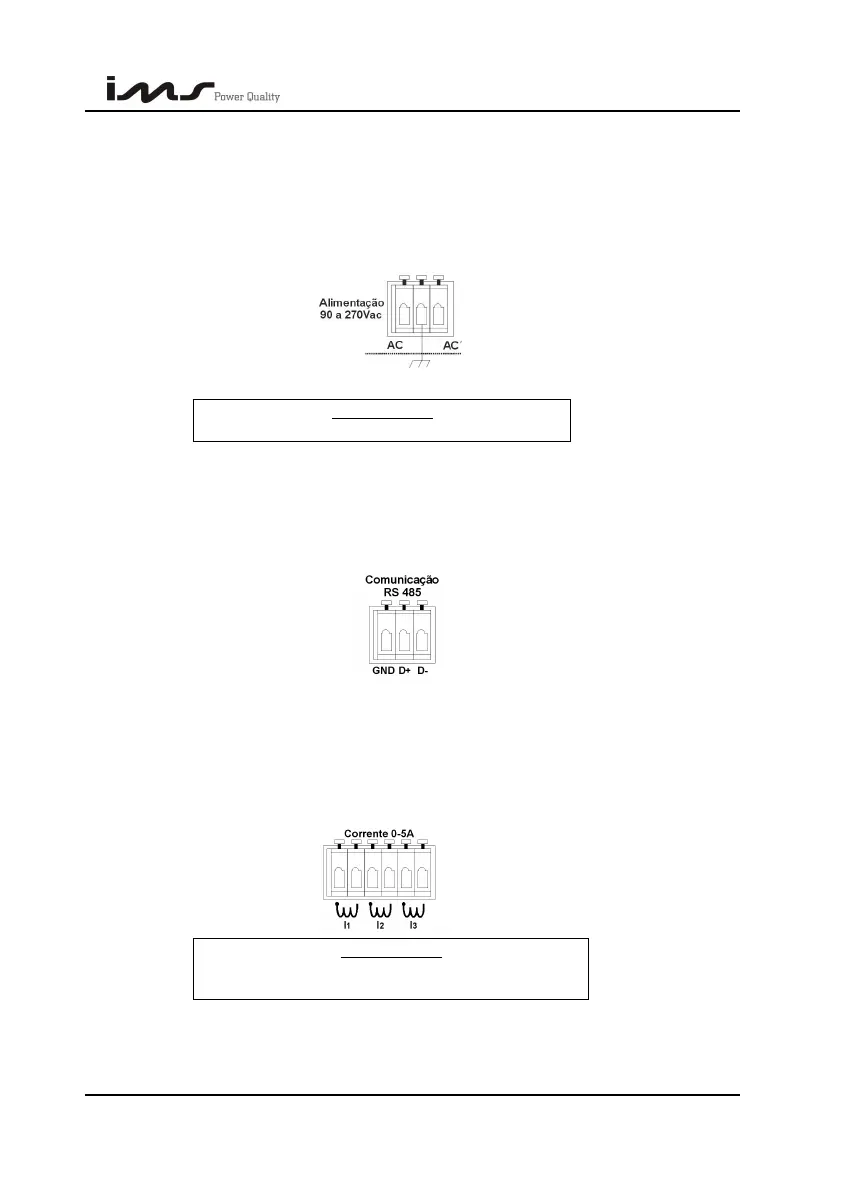
3.2.1. FEEDING CONNECTOR
It is the connector where it should be connected the energy that feeds the Smart Cap
485. In this connector there isn’t any connection with the monitored voltage, serving only to
feed the equipment.
It is recommended the use of earthing, staying as criterion of each installation.
IMPORTANT:
Feeding Maximum Voltage: 270Vca.
3.2.2. SERIAL COMMUNICATION CONNECTOR RS485
In terminals indicated by D+ and D- it is made the connection with the equipments net
(RS485). Verify the correct cable polarity, when the connection is made. The connection of
the earthing terminal (GND) generally is not necessary.
3.2.3. CURRENT SENSORS CONNECTOR
There are 6 terminals where it should be connected the current inputs, being a pair of
terminals for each CT.
Usually, this connection is made through current transformers (CT’s). If there are not CT
the connection should be made directly. Respecting the maximum limit of 5A.
IMPORTANT:
The current, in this connector, should not surpass
5A.
SMART CAP 485 37