Manual de Instalação e Operação
Each actuation output has capacity to actuate contactors with up to 105VA of power and
starting current smaller or equal to 10A. For example: contactors model Siemens 3TF54/55,
WEG CW297/22, INEPAR JMC300, Scheneider-Telemecanique LC1F330 or equivalents or
smallers.
NT
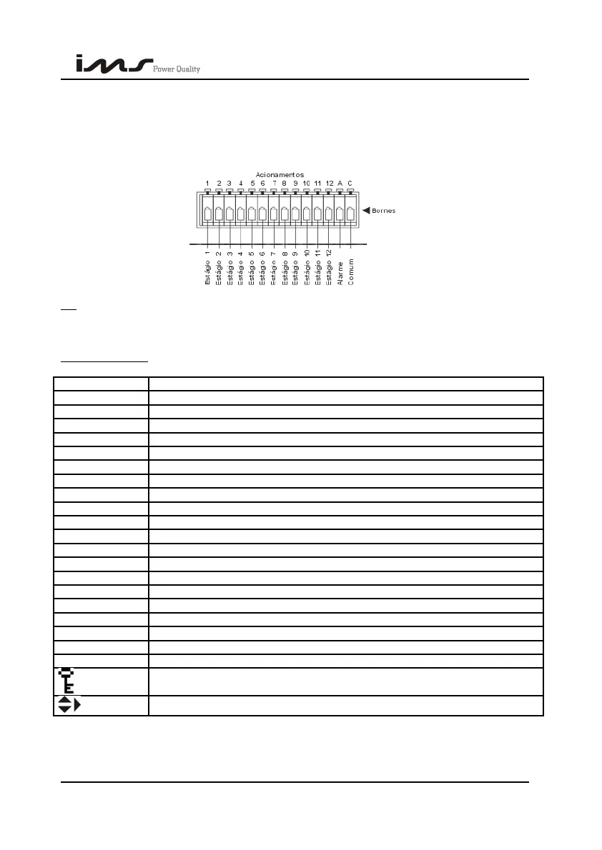
Acionamentos = Actuations, Bornes = Terminals, Estagio n = Step, Alarme = Alarm, Comum
= Common.
5. SYMBOLOGY
On: It means that the output of this stage is connected.
Off: It means that the output of this stage is disconnected.
Disabled: It means that the output of this stage is disabled.
F1,...,F6: It indicates the key name.
FP: Power factor.
V: Voltage.
A: Current.
W: Active power.
VA: Apparent power.
VAr: Reactive power.
Hz: Frequency.
i: Inductive.
c: Capacitive.
%: Percentile.
N: Neutral.
AC e AC´: They are the inputs of the feeding device.
V1,V2 e V3: They are the inputs of the voltage measurement (sensoring)
I1, I2 e I3: They are the inputs of the current measurement (sensoring)
A: Output for control of an external alarm device.
C: It represents the outputs common.
1 a 12: They represent the control outputs of the capacitors banks.
:
Indication of protected keyboard.
:
Arrows that indicate more screens inside a menu.
On: It means that this stage output is connected.
Off: It means that this stage output is disconnected.
SMART CAP 485 43