42
CD1-a
Chapter 8 – Appendix
3 - ADJUSTMENT TO VARIOUS MOTOR TYPES
3.1 - MOTOR THERMAL SENSOR
The thermal probe is connected to the X1 resolver connector, pins 1 and 2.
3.1.1 - PTC OR NTC THERMAL PROBE
The PTC or NTC configuration is made by means of the VISUAL DRIVE SETUP software.
o PTC sensor: the triggering will occur at a value of about 3.3 kOhms of the thermal sensor resistor, that is
140°C.
o NTC sensor: the triggering will occur at a value of about 3.3 kOhms of the thermal sensor resistor, that
is 140°C.
3.2 - I
2
t PROTECTION
Current limitation in Fusing mode
If the RMS current as not dropped below 85 % of the rated current after 1 second, the I
2
t fault is released and the
amplifier disabled.
When the amplifier RMS current (I
2
t) reaches the Rated current value, the I
2
t protection limits the amplifier
current at this value.
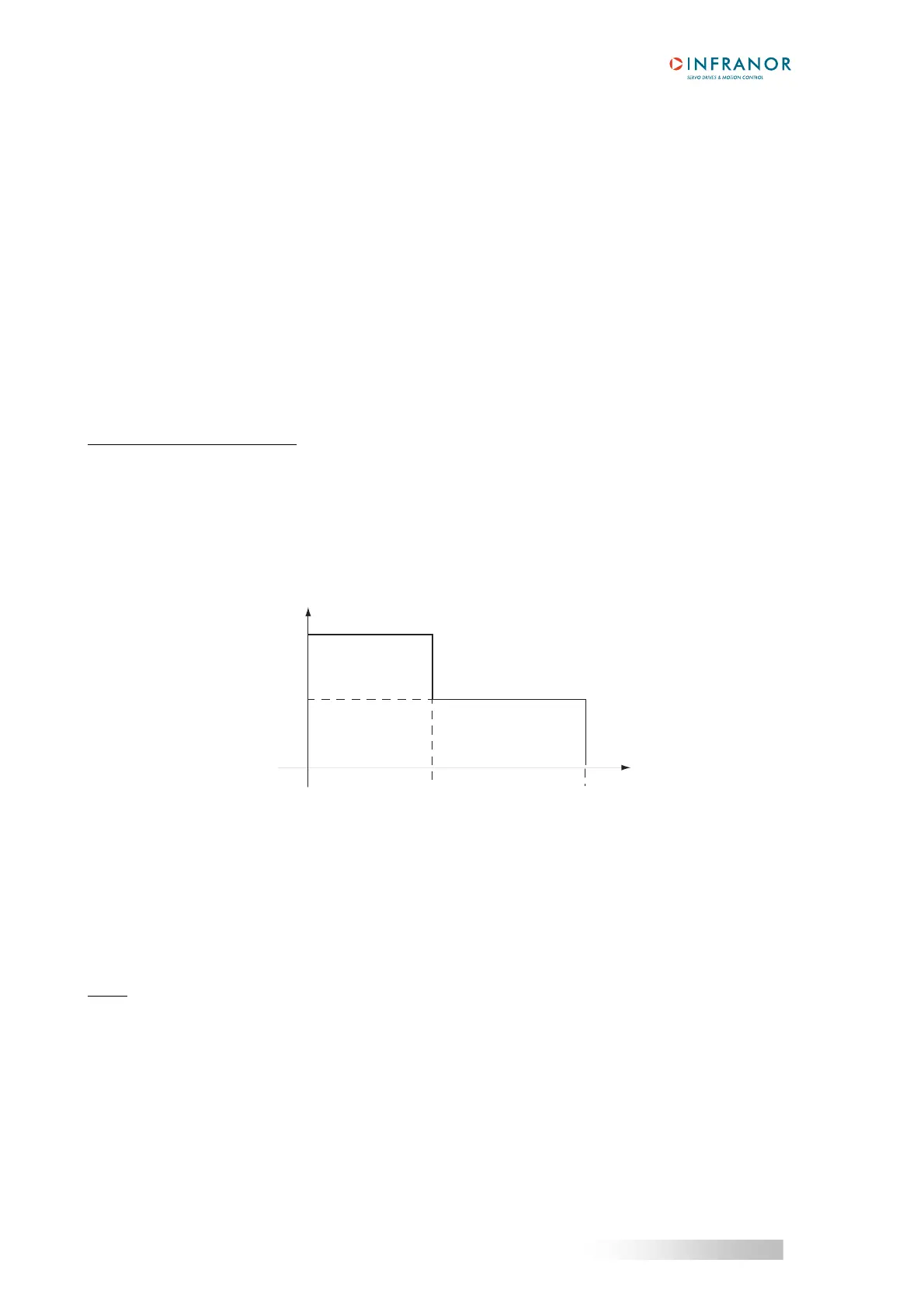
The amplifier current limitation diagram in an extreme case (motor overload or locked shaft) is shown below:
t0
t2 t3
Rated current
Maximum current
Amplifier current
t2 = current limitation
t3 = I
2
t fault
Time
The maximum current duration before limitation at the rated current depends on the value of the Rated current
and Maximum current parameters. This value is calculated as follows:
Tmax (second) = (t2 - t0) = 4 x [Rated current (%)]
2
/ [Maximum current (%)]
2
The current limitation duration before the release of the protection is depending on the value of the Rated current
and Maximum current parameters:
Tlim (second) = (t
3 - t2) = 1 - 0.7 x [Rated current (%)]
2
/ [Maximum current (%)]
2
NOTE
- These formula are correct for a Maximum current / Rated current ratio > 1.5.
- When the Maximum current / Rated current ratio = 1, there is no interruption and the current is maintained
at the rated current value.
- The I
2
t signal can be displayed by means of the digitizing oscilloscope available in the Visual Drive Setup
software.
Current limitation threshold (%) = [Rated current (%)]
2
/ 50
Rated current (%) = [(I
2
t signal value (%)) x 50]
1/2