21
CD1-a
Chapter 3 – Inputs-Outputs
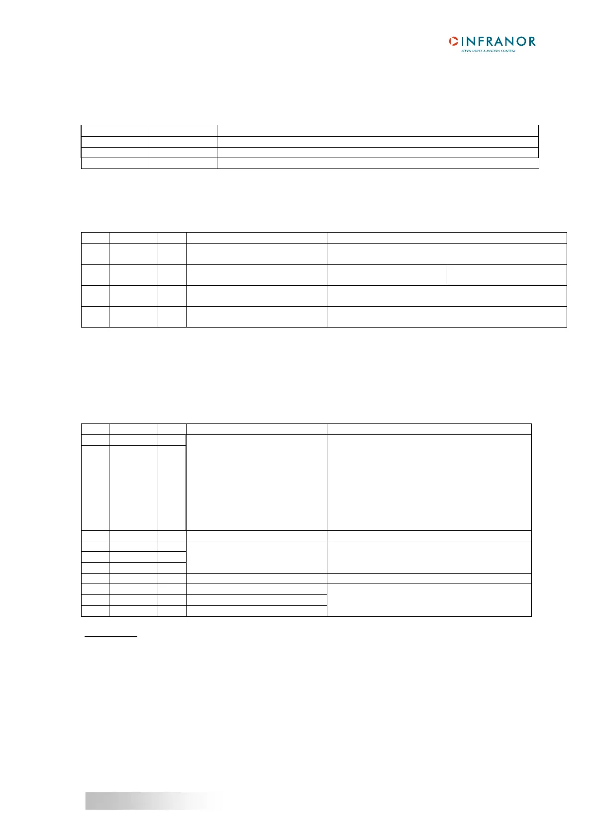
4 - X5 SERIAL LINK
Sub D 9 pins male (female connector is not supplied)
PIN FUNCTION REMARKS
5 0 Volt GND (connection of the shield if no "360°" connection on the connector)
3 TXD Transmit data RS 232
2 RXD Receive data RS 232
5 - X8: AUXILIARY SUPPLY CONNECTOR
4 pins male connector (with 5.08 mm pitch) - Female connector supplied
Fastening torque of the connector screws: 0.5 Nm
PIN SIGNAL I/O FUNCTION DESCRIPTION
1 GND I Potential reference of the
24 V
DC supply
GND = earthed potential reference
2 +24 VDC I 24 VDC auxiliary supply isolated
from the mains
24 VDC +/-15 % - 0.320 A
Regulation with load: 3 %
UL protection by
4 A UL fuse
3 Brake+
24 V
O
Brake is not available on amplifier version CD1-a
4 Brake-
O
Brake is not available on amplifier version CD1-a
6 - X9 POWER CONNECTOR: MAINS, MOTOR, BRAKING RESISTOR (CD1-a-230 V AND 400 V)
CD1-a-230/I: 10 pins male connector (with 5.08 mm pitch) - Female connector supplied
CD1-a-400/I: 10 pins male connector (with 7.62mm pitch) - Female connector supplied
Fastening torque of the connector screws: 0.5 Nm
PIN SIGNAL I/O FUNCTION DESCRIPTION
1 RB O
2 RB O
Power feedback during the motor
deceleration with high inertia and
speed
CD1-a-230/I: 100 Ohms/100W
(dp 100/100)
CD1-a-400/1.8 to 7.2: 200 Ohms/100W
(dp 200/100)
CD1-a-400/14: 50 Ohms/200 W
(dp 50/200)
CD1-a-400/30 and 45: 33 Ohms/280W
(dp 33/280)
(Braking resistors must be ordered separately)
3 DC- I/O Parallel connection of the DC bus Only available on UL listed drives
4 L1 I
5 L2 I
6 L3 I
Mains input
Mains filter integrated in the
amplifier
CD1-a-230/I 230 V
AC 1~ or 3~
CD1-a-400/I 400 to 480 V
AC 3~
7 DC+ I/O Parallel connection of the DC bus Only available on UL listed drives
8 W O Motor phase W
9 V O Motor phase V
10 U O Motor phase U
Motor cable with earthed connection by means of
Faston socket and 360° shield connection on
earthed collar
IMPORTANT
: The motor cable must be shielded and connected over 360° on collars mounted for this purpose on
the housing. The earth wire of the motor cable MUST be connected to the Faston socket marked with the GND
sign.
The earth reference must also be connected on the second Faston socket.
The installer of the drives has to use a UL Listed Quick connect for ground connection (0.250 inches or 6.35
mm wide nominal).
Field wiring terminals have to use copper conductors only.
Torque value for field wiring terminals: value to be according to the Recognized terminal block used.