9
CD1-a
Chapter 2 - Specifications
Chapter 2 - Specifications
1 - TECHNICAL SPECIFICATIONS
1.1 - CD1-a-230/I AMPLIFIER
Mains operating power supply 230 VAC +10 % / -15 %, 1~ or 3~, 50 - 60 Hz
Isolated galvanic auxiliary supply voltage 24 VDC +/- 15 % - 320 mA
Motor phase-phase output voltage 200 Vrms
Integrated braking system External 100 Ohm / 100 W resistor (dp 100/100)
Minimum resistance: 50 Ohm (dp 50/200)
Minimum inductance between phases 1 mH
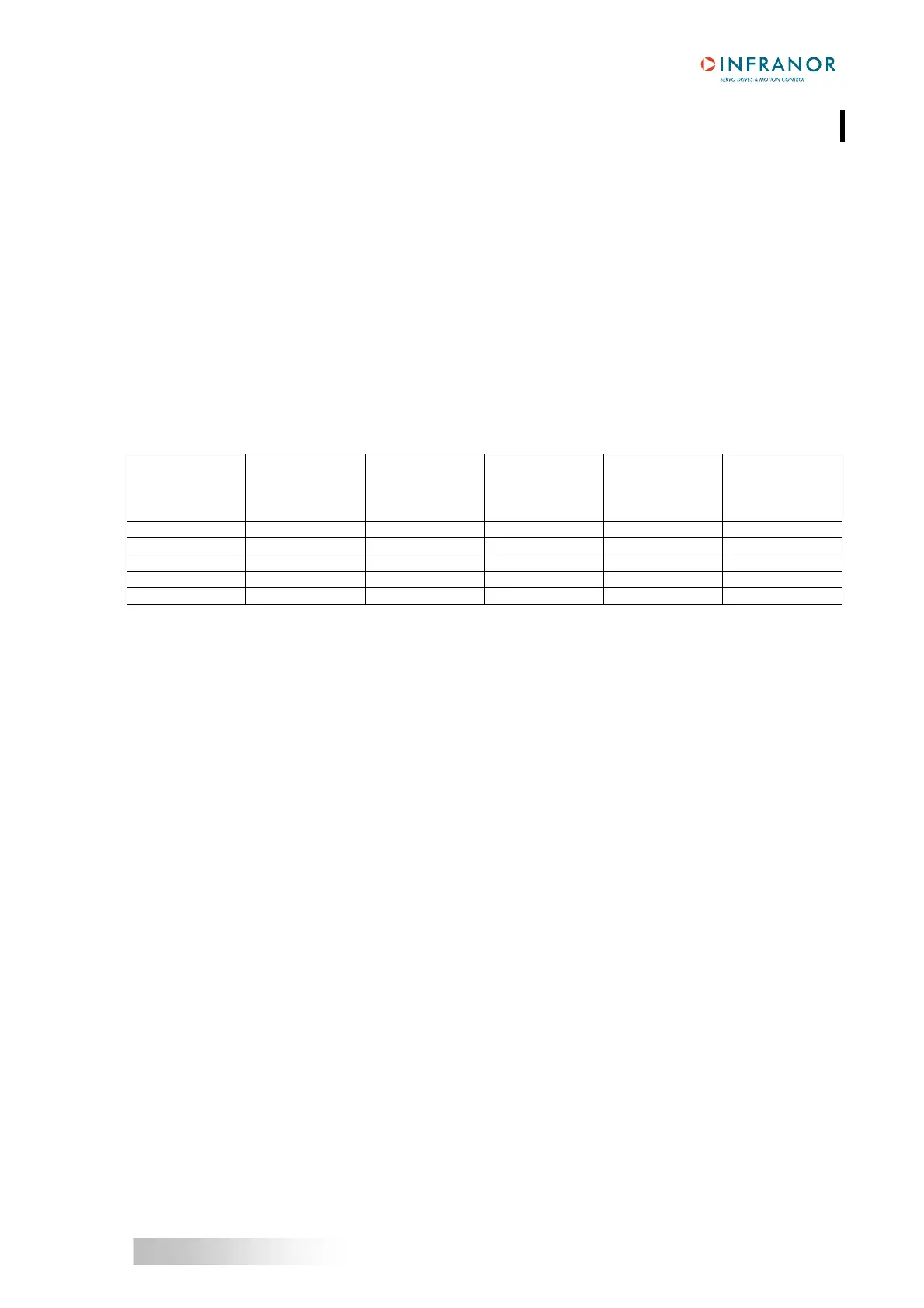
Amplifier output current ratings
AMPLIFIER
TYPE
U rated
(Vrms)
Imax (Arms)
+/-5 %
1 s
Max. rated
current
of the amplifier
(A rms)
Power losses
(W)
UL compliance
CD1-a-230/2.25 230 2.25 1.1 25 yes
CD1-a-230/4.5 230 4.5 2.25 30 yes
CD1-a-230/7.5 230 7.5 3.75 44 yes
CD1-a-230/10.5 230 10.5 5.25 55 yes
CD1-a-230/16.5 230 16.5 8.25 66 yes
Maximum room temperature = 40° C.
1.2 - CD1-a-400/I AMPLIFIER
Mains operating power supply voltage 400 to 480 VAC + 10 %/- 15 % 3~, TN or TT system with
earthed neutral point, 50 - 60 Hz
(Phase/Ground voltage must be balanced)
Isolated auxiliary supply voltage 24 V
DC +/- 15 % - 320 mA
Motor phase-phase output voltage 380 to 460 Vrms depending on the mains
Integrated braking system CD1-a-400/1.8 to 7.2 A:
External 200 Ω/100 W resistor (dp 200/100)
CD1-a-400/14:
External 50 Ω/200 W resistor (dp 50/200)
CD1-a-400/30 and 45:
External resistor 33 Ω/280 W resistor (dp 33/280)
Minimum inductance between phases 2 mH