19
CD1-a
Chapter 3 – Inputs-Outputs
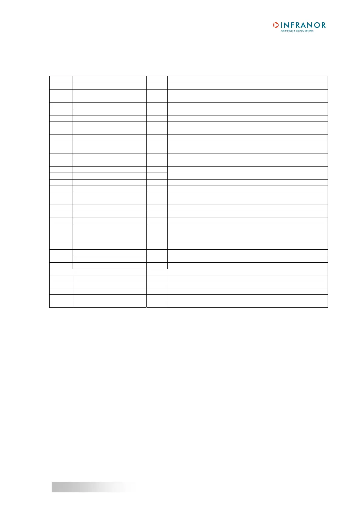
3 – X2: COMMAND CONNECTOR, LOGIC INPUTS-OUTPUTS AND ENCODER
Sub D 25 pins male (female connector is not supplied)
Pin Function I / O REMARKS
1 FC+: Limit switch + I Positive logic, optocoupled input, galvanic insulation
14 FC-: Limit switch - I Positive logic, optocoupled input, galvanic insulation
24 Ref. inputs I Supply reference of the galvanic insulated logic inputs
20 ENABLE I Positive logic, optocoupled input, galvanic insulation
23 Ref. inputs I Supply reference of the galvanic insulated logic inputs
2 Current command CI I Positive logic, optocoupled input, galvanic insulation
10 CV0 Zero speed input
command
I Positive logic, optocoupled input, galvanic insulation
25 GND I GND reference of the earthed amplifier
13 RESET I Positive logic, optocoupled input, galvanic insulation
Inhibition of the faults memory stored in the amplifier
12 Ref. inputs (0 Volt) I Supply reference of the galvanic insulated logic inputs.
17 CV+ Input command CV + I ± 10 V speed input command for max. speed
16 CV- Input command CV - I or ± 10 V current input command for Imax with "CI" input active
15 GND I GND reference of the earthed amplifier
3 I limit current limitation I Analog input for external max. current limitation
0 to 10 V for 100 % to 0 % of Imax
11 Reserved input I
Do not use (to be used by INFRANOR only)
18, 19 AOK: amplifier ready O Relay contact: closed if amplifier OK, open if fault.
Protection against overvoltages by bidirectional TRANSIL
Pmax = 10 W with Umax = 50 V or Imax = 100 mA
21 + 12 Volts O Output impedance: 47 Ohms. Max. 50 mA available
22 - 12 Volts O Output impedance: 47 Ohms. Max. 50 mA available
4 Z/ O Differential output of Z/ encoder marker pulse (max. 5 V, 20 mA)
5 Z O Differential output of Z encoder marker pulse (max. 5 V, 20 mA)
6 A/ O Differential output of encoder A/ channel (max. 5 V, 20 mA)
7 A O Differential output of encoder A channel (max. 5 V, 20 mA)
8 B/ O Differential output of encoder B/ channel (max. 5 V, 20 mA)
9 B O Differential output of encoder B channel (max. 5 V, 20 mA)