43
CD1-a
Chapter 8 - Appendix
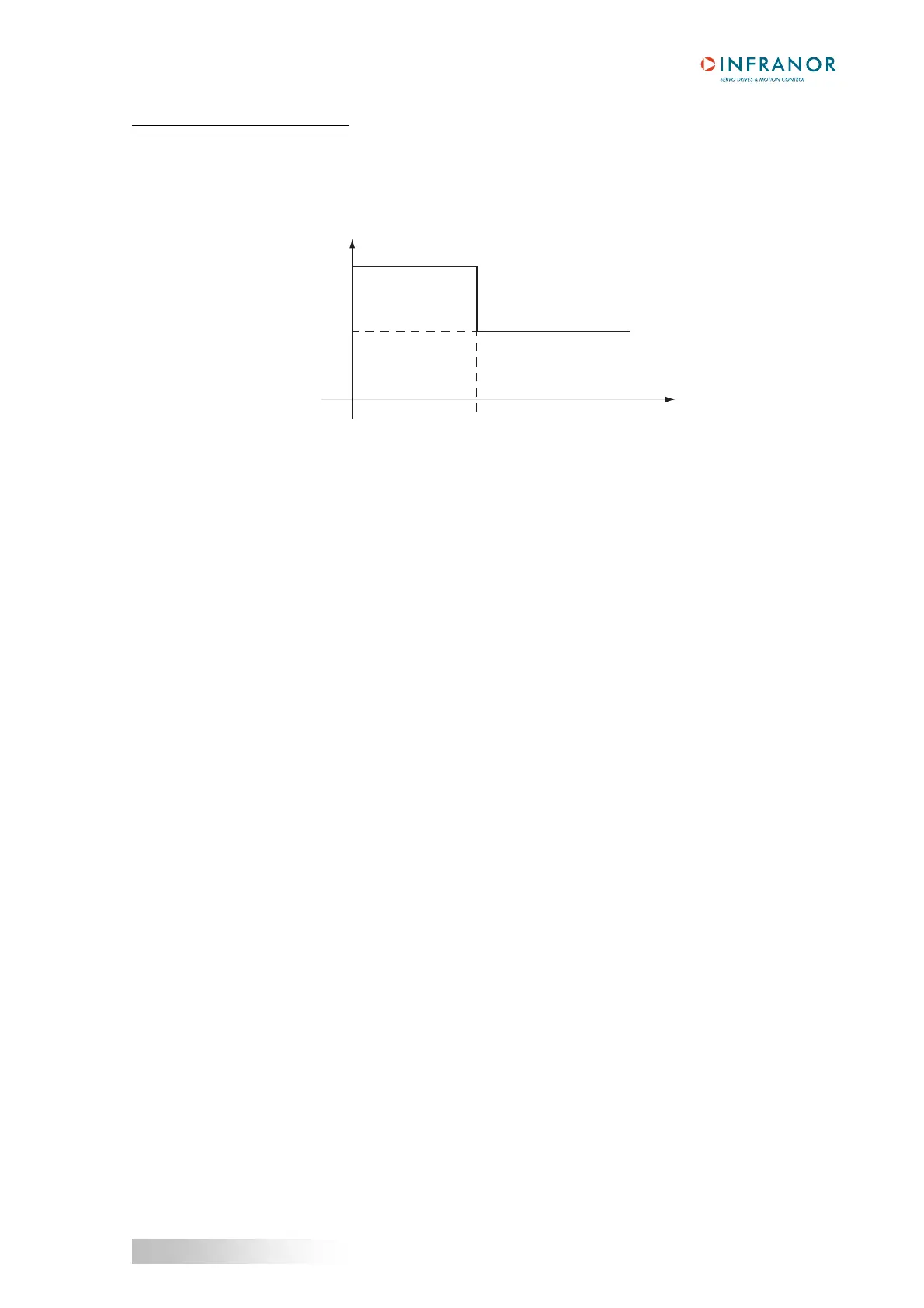
Current limitation in Limiting mode
When the amplifier RMS current (I
2
t) reaches the Rated current value, the I
2
t protection limits the amplifier
current at this value.
The amplifier current limitation diagram is shown below.
t0
t2
Rated current
Maximum current
Amplifier current
t2 = current limitation
Time
The maximum current duration before limitation at the rated current (t2 - t0) is calculated the same way as for the
Fusing mode.
4 - USE OF THE "LIMIT SWITCH" INPUTS
Response time = 500 µs.
During the amplifier operation in speed mode (CI logic input inactive) or in torque mode (CI logic input active), the
enabling of the FC+ limit switch inhibits any CW motor rotation and the enabling of the FC- limit switch inhibits any
CCW motor rotation.
5 - USE OF THE "CV0" INPUT
Response time = 500 µs.
During the amplifier operation in speed mode (CI logic input inactive), the activation of the CV0 input stops the
axis rotation (the deceleration time is depending on the value of the Accel/Decel time value).
During the amplifier operation in torque mode (CI logic input active), the enabling of the CV0 input assigns a zero
current input command and the current reference is maintained at zero as long as the CV0 input is active.
6 - USE OF THE "AOK" OUTPUT
If any fault occurs, the amplifier is disabled.
If a fault occurs (except for the "Undervot." fault) the AOK relay contact opens.
Use the AOK relay contact as described in chapter 3, section 3.3 in order to allow the power voltage to be
switched on after the initialization phase.
7 - USE OF THE "RESET" INPUT
If the position initialization references must be kept when a stored fault is released on the amplifier or when the
power supply is cut-off, it must be possible to reset the faults via pin 13 of X2 without switching off the auxiliary 24
V
DC supply or to backup the 24 VDC supply by means of a 24 VDC battery (see chapter 4).