41
CD1-a
Chapter 8 - Appendix
2 - ADJUSTMENT TO VARIOUS RESOLVER TYPES
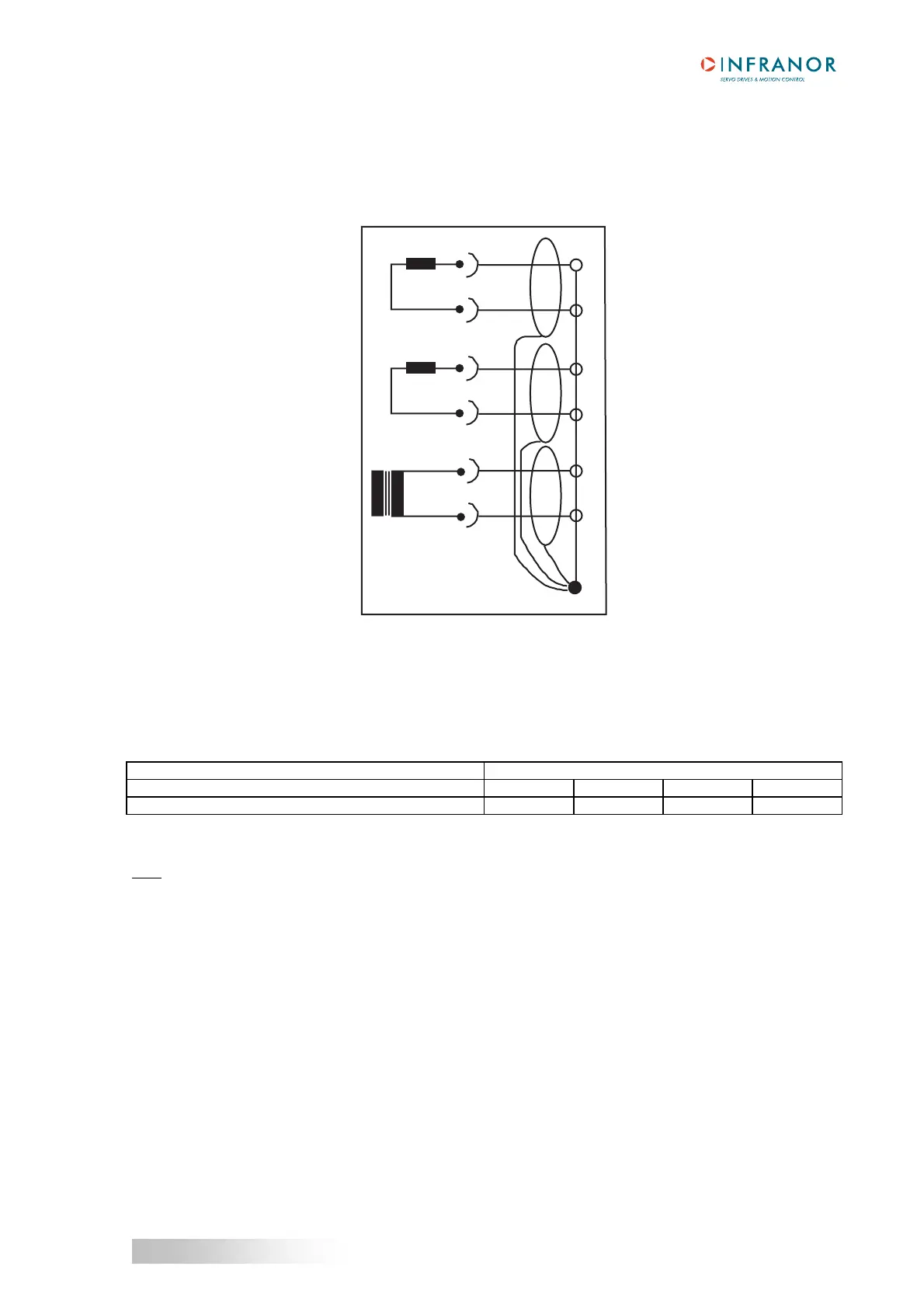
For the use of other resolvers than those mounted on MAVILOR motors, see following wiring diagram of the X1
connector as well as the manufacturer's diagram:
X1
8
4
7
3
9
5
6
S1
S3
S2
S4
R1
R2
Si n
Co s
Re f
Ye
Re
Br
Bk
Bk/ Wh
Re / W h
Bk = black Re = red
Bl = blue Wh = white
Br = brown Ye = yellow
For the use of resolvers with transformation ratios others than 0,5, the Cos and Sin signal amplitude must be
adjusted by means of the "P-RES" components according to the table below:
P-RES
TRANSFORMATION RATIO 0,3 0,45 0,5 1
A - B - C - D (tolerance < 1 %) 21 K 14,3 K 12,7 K 6,34 K
This adjustment is factory set by INFRANOR.
Note
When using resolvers with a number of pole pairs N > 1, all speed values displayed in the amplifier are equal to N
times the motor rotation speed.