23
Chapter 4 - Connections
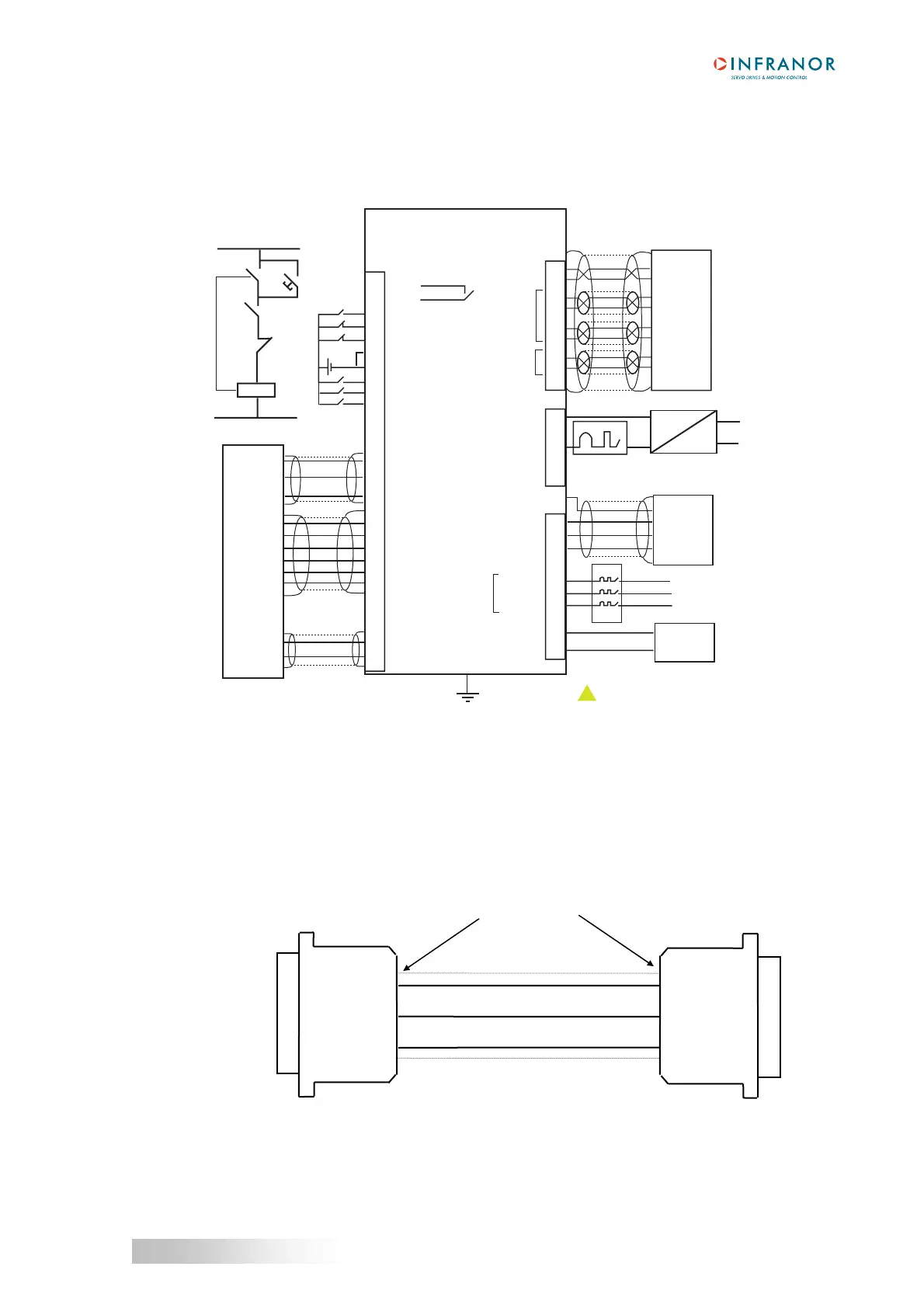
CD1
a
1.2 - CD1-a-400/I AMPLIFIER
(See chapter 4, section 3.5 for the UL compliant connection).
3
7
4
8
5
9
6
1
2
3
1
2
H
I
D
C
A
B
E
F
X1
X2
4
X8
X9
10
9
8
7
6
5
4
3
2
1
A
B
C
D
dp
*
24V
18
19
20
1
14
24
23
2
10
13
17
5
16
15
4
6
7
8
9
/A
A
/B
B
/Z
Z
24V
3
25
CD1-a-400/I
AOK
AOK/
ENABLE
FC+
FC-
REF INPUTS
REF INPUTS
CI
CV0
RESET
CV+
CV-
GND
ILIMIT
+24 Vdc
!
24 Vdc
3A
AC
230 Vac
-
+
+/-15%
**
ENABLE
relay
Motor temp.
Motor temp.
Resolver
signal
Resolver
reference
GND
GND
GND
RESOLVER
MAVILOR
GND
Power relay
remote control
Power
ON
AOK
Power
OFF
Power
relay
NC
Analog
speed input
command
Position
counting
Motor U phase
Motor V phase
Motor W phase
DC+
DC-
400 Vac L3
400 Vac L2
400 Vac L1
400 Vac
three-phase
Braking resistor
Braking resistor
Braking
resistor
Mains
3x400V/480V
MOTOR
Power
relay
GND
*
CD1-a-400/1.8 to 7.2 : dp 200/100
CD1-a-400/14 : dp 50/200
CD1-a-400/30 and 45: dp 33/280
Circuit breaker curve D
I1s = 10 x In
** 10 A for I < or = 14 A
20 A for I = 30 and 45 A
isolated
The protection, on source side, of both 24 V and power supplies must be made by the user.
1.3 - SERIAL LINK CONNECTION
CD1-a
X5
PC
Serial port
360° shield connection
Sub D 9pts female
Sub D 9pts female
RxD 2
TxD 3
GND 5
5 GND
2 RxD
3 TxD