Home
Ingenico
Touch terminals
iUI120
Ingenico iUI120 User Manual
4
of 1
of 1 rating
58 pages
Give review
Manual
Specs
To Next Page
To Next Page
To Previous Page
To Previous Page
Loading...
Intégration Guide_iUI120
19/58
Copyright © 2013 Ingenico
900016253 R11 000 01/1416
All rights reserved
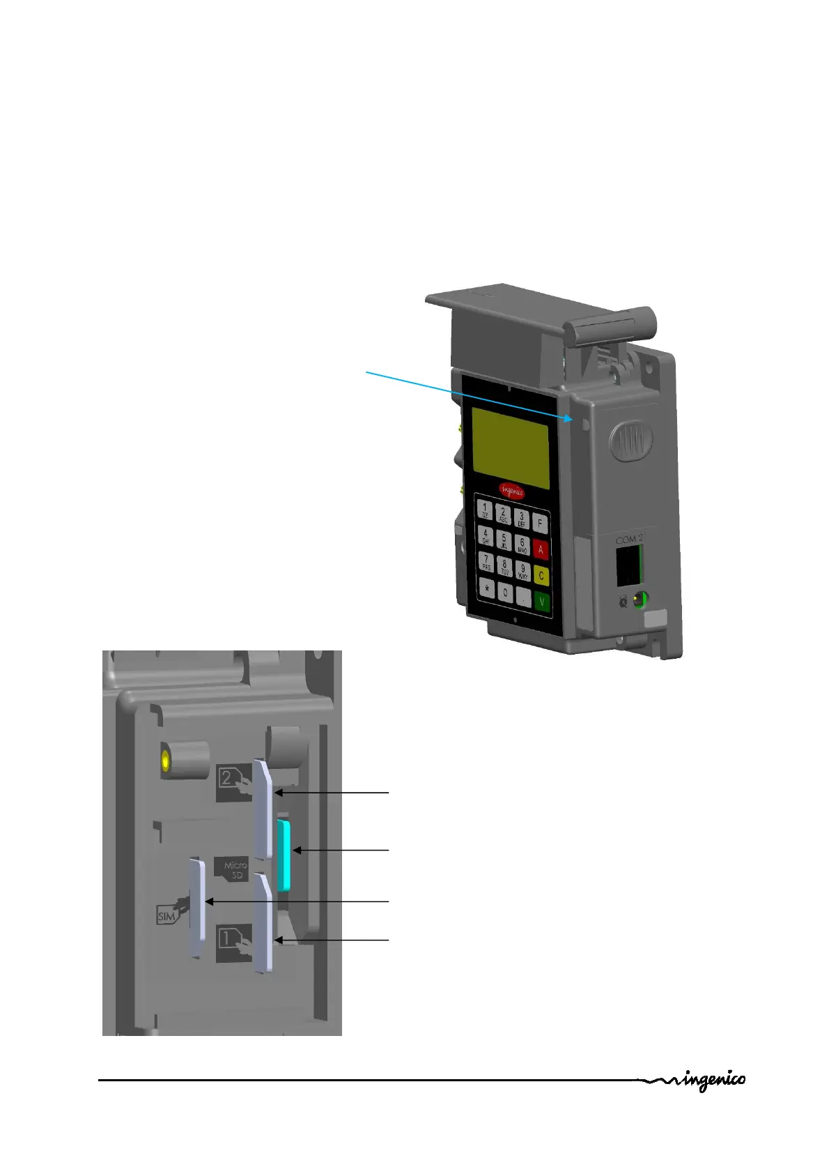
1.3.3.11
SAM & µ
SD Ins
tallation
1.
Disconnect
the iUI120 unit from the main power supply.
2.
Open the SA
M door by removing the screw.
3.
Insert the SAM ca
rds in SAM slot 1 and /or slot 2
4.
Insert µ
SD card
in µSD slot
5.
Insert SIM card
in SIM slot.
6.
Slide the SAM door a
nd screw.
SAM cover
Screwed with M2X6 T6
SIM Slot
SAM1 Slot
µ
SD Slot
SAM2 Slot
2
18
20
Table of Contents
Default Chapter
3
Table of Contents
3
1 General
6
Definition of Acronyms
6
Iui120 Payment Solution Presentation
7
Diagram of Iui120 Connectivity and Communications
8
Services
9
Description of Iui120 Product
10
Iui120 Product Views
10
Iui120 Technical Hardware Characteristics
11
Iui120 Output Connectors Description
13
Ethernet
15
USB Device
15
USB Host
15
COM0 Link
15
COM2 Link (Optional)
15
MDB Slave
16
MDB Master (Optional)
16
Wake-Up Jack
17
Bluetooth (Optional)
17
GPRS (Optional)
18
SAM & Μsd Installation
19
Buzzer
20
Display
20
Maintenance Button and LED
20
Iui 120 Keypad
21
Cable Protection
22
Antenna Installation
23
Professional Installation Requirement
24
Wake-UP Function a Revoir
25
Wake-Up Mechanism Iui120 Unit
25
Recommended Circuit Implementation
26
Power-On Sequence Iui120/Iur250/Iuc150
27
2 Main Accessories
28
Generality
28
Optional USB Cable
28
Serial Cable
28
LLT Cable
29
Stand-By Management Cables
30
Jack Connector
30
COM0 and COM2
30
3 Iui120 Software
31
Software Architecture
32
Secure Management of Software
33
Operating System
34
Telium Manager
35
Software Downloading
37
Development Station
40
4 Terminal Management System
42
Introduction
42
Basic Functions
42
Advanced Functions
42
Customers Savings with Ingenico TMS Solution
42
5 Installation Procedure in Kiosks
43
Security Requirement Iui120
43
General Installation Recommendations
44
6 Assembly Procedure for Iui120
45
Kiosk Minimum Volume for Iui 120
45
Volume for Iui 120 Without Cable Gasket
45
Volume for Iui 120 with Cable Gasket
46
Kiosk Preparation for Iui120 New Installation
47
Installing the Iui120 in New Kiosk
48
Left Horizontal on a Shelve Inside the Kiosk
48
Mounted Vertically on a Support Using EVA Standard Recommendation
48
Mounted Vertically on a Support Using Bolds or Studs
50
7 Maintenance
52
Configuration
52
Operating Life
52
8 Cleaning Instructions
52
9 Disassembling the Products According to Weee Directive
53
Iuc120 End-Of-Life Disassembly Instructions
53
Models and Descriptions
53
Components and Materials Requiring Selective Treatment
53
Product Disassembly Process
54
10 Standards
55
Electrical Consumptions
55
Temperature and Humidity
55
Environmental Specification Continued
55
EC Standard Compliance Marking
56
IC Statements
56
FCC Statement
57
Environment (WEEE, Batteries and Packaging)
58
4
Based on 1 rating
Ask a question
Give review
Questions and Answers:
Need help?
Do you have a question about the Ingenico iUI120 and is the answer not in the manual?
Ask a question
Ingenico iUI120 Specifications
General
Card Reader
Magnetic stripe
Battery
Removable rechargeable battery
Payment Options
Credit/Debit cards
Security
EMV Level 1 & 2
Ports
USB
Related product manuals
Ingenico iSMP4
31 pages
Ingenico iCMPsi
30 pages
Ingenico iPP320
57 pages
Ingenico IWL 250
42 pages
Ingenico iCT 250
33 pages
Ingenico AMEX iCT220
16 pages
Ingenico Lane/7000
28 pages
Ingenico Link/2500
44 pages
Ingenico Lane 3000
44 pages