2‐4‐2 PRINTINGGANTRY’SMOVEMENTINYDIRECTION
Main Parts Included
1. Step Motor: It generates the rotation of leading screw.
2. Leading Screw: It leads the movement of printing gantry, which is bound to two plates that are fixed on the
bearing brackets of the leading screw.
3. Linear Guide and Guide Slider: Two linear guides are installed, one on each side of the leading screw to
guide the movement of printing gantry and make sure its passage is linear. One each linear guide, there
are four guide sliders, two for each connecting plate.
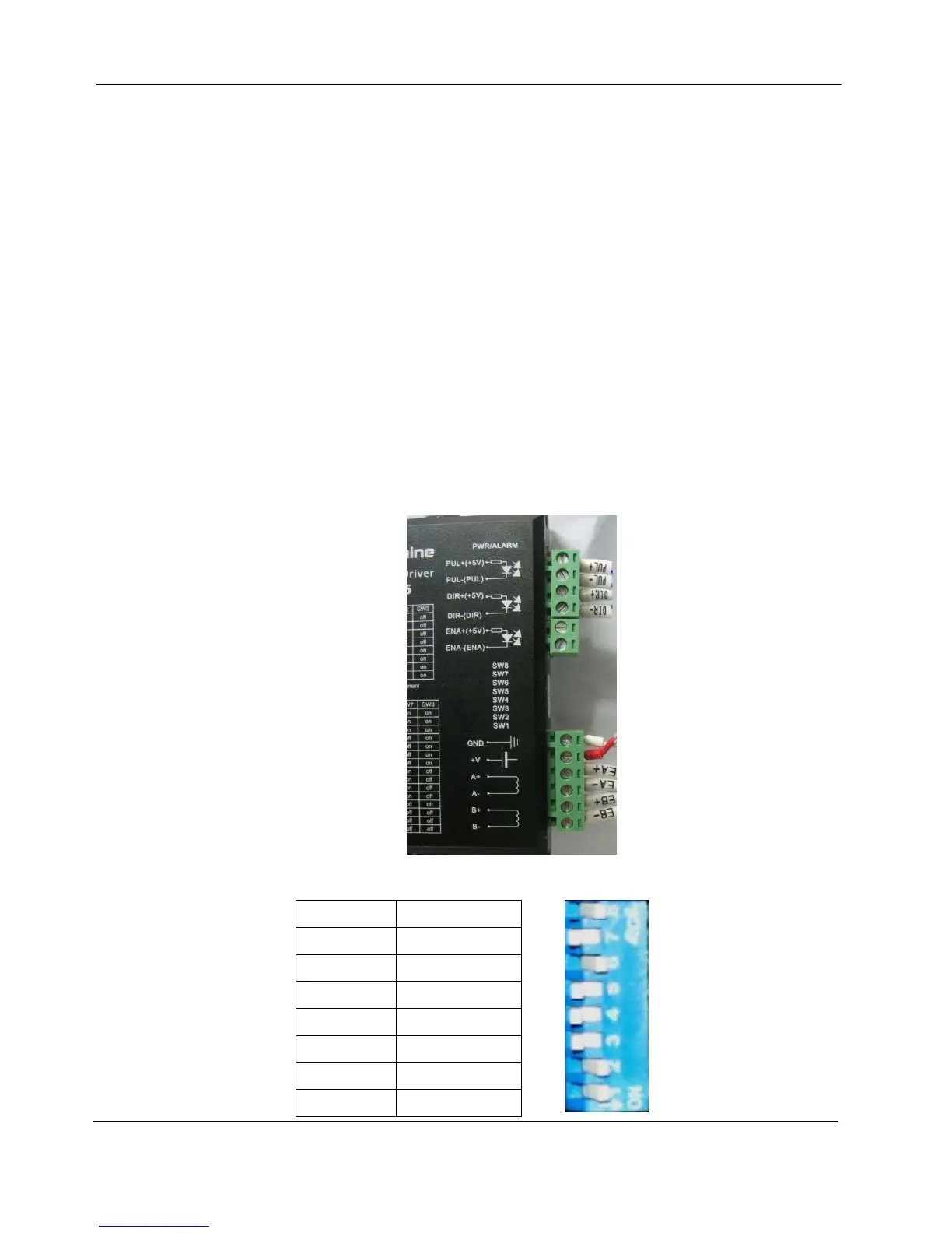
4. Step Motor Driver: It sits in the front electric cabinet. It controls and drives the step motor of printing
gantry’s movement in Y direction.
1) Two connectors are plugged on the step motor driver. The signal cables (PUL+, PUL-, DIR+ and DIR-)
go to the main board, encoder and high voltage cables (EB+, EB-, EA+, EA-, +5V and GND) come
from the step motor.
2) Dial Switch:
SW8 ON
SW7 OFF
SW6 ON
SW5 OFF
SW4 OFF
SW3 OFF
SW2 ON
SW1 ON