MD320/MD320N User Manual Parameter Description
101
Two PWM carrier frequency adjustment modes, xed and random, are provided. The random
PWM motor noise has wide frequency range, while the fixed PWM motor noise has fixed
frequency.
When the carrier wave temperature adjustment is active, the inverter can automatically adjust
the carrier frequency according to its temperature. This function can reduce the possibility of
overheating alarm of the inverter.
F0-17
Speed-up time 1 Factory default value 20.0s
Setup range 0.0s
~
6500.0s
F0-18
Speed-down time 1 Factory default value 20.0s
Setup range 0.0s
~
6500.0s
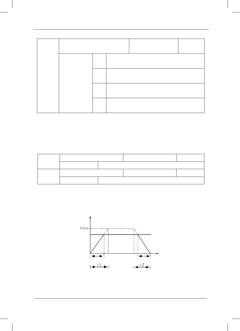
Speed-up time 1 refers to the time “t1” required for the inverter to speed up from 0Hz to the
maximum output frequency (F0-10).
Speed-down time 1 refers to the time “t2” required for the inverter to Speed down from the
maximum output frequency (F0-10) to 0Hz, as shown in the following gure:
S e tting
Frequency
Output Frequency
Ac t u a l AccelerationTim e
Actual DecelerationTi m e
Tim e
S e tting AccelerationTim e
Setting DecelerationTim e
Pay attention to the difference between the actual acceleration/deceleration time and the setup
acceleration/deceleration time.
Fig.6-1 Schematic diagram for acceleration/deceleration time
F0-16
Carrier frequency adjustment
selection
Factory default value 0
Setup range
0
Fixed PWM, and carrier frequency temperature
adjustment inactive.
1
Random PWM, and carrier frequency temperature
adjustment inactive.
2
Fixed PWM, and carrier frequency temperature
adjustment active.
3
Random PWM, and carrier frequency temperature
adjustment active.
 Loading...
