Where,
SB1: Stop button
SB2: Running button
Dln is multifunctional input terminals of DI1 to DI5 (DI1 to DI10 if multifunctional input and
output expansion card is selected). In this way, it shall define the corresponding terminal
functions as No.3 function “Three-line Mode running Control”.
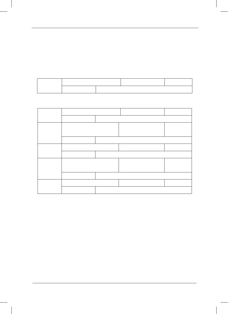
F4-12
Terminal UP/DOWN Speed Factory default value 1.00Hz/s
Setup range 0.01Hz/s ~ 100.00Hz/s
Terminals UP/DOWN is used to adjust the change rate when setting the frequency.
F4-13
AI1 minimum input Factory default value 0.00V
Setup range 0.00V~ 10.00V
F4-14
AI1 minimum input
corresponding setup
Factory default value 0.0%
Setup range -100.00%~ 100.0%
F4-15
AI1 maximum input Factory default value 10.00V
Setup range 0.00V ~ 10.00V
F4-16
AI1 maximum input
corresponding setup
Factory default value 100.0%
Setup range -100.00% ~ 100.0%
F4-17
AI1 input lter time Factory default value 0.10s
Setup range 0.00s ~ 10.00s
The above function codes define the relationship between the analog input voltage and
analog input setup value. When the analog input voltage exceeds the setup maximum input or
minimum input range, the excess part will be calculated as maximum input or minimum input.
When the analog input is current input, 1mA current equals to 0.5V voltage.
In difference applications, 100% of analog input corresponds to different nominal values. Refer
to all the application parts for details.
Several setting examples are shown in the following gures:
 Loading...
