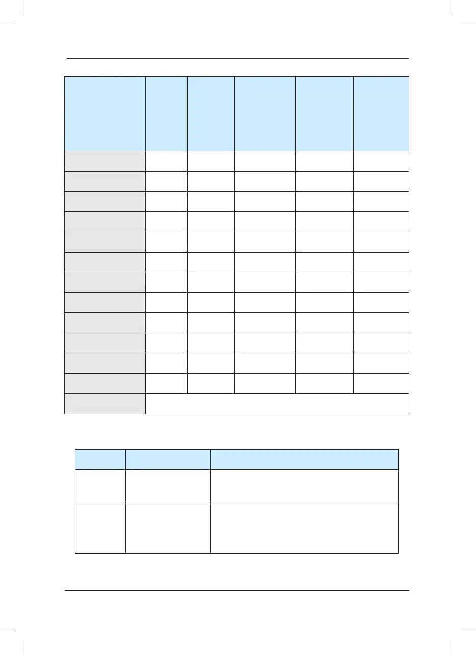
Table 3-2 Instruction for the Use of External Electrical Parts of MD320
Inverter Model
Circuit
Breaker
(MCCB)
(A)
Recomm
ended
Contactor
(A)
Recommend-
ed
Conducting
Wire of Main
Circuit at the
Input Side
(mm)
Recomm
-ended
Conducting
Wire of Main
Circuit at the
Output Side
(mm)
Recomme-
nded
Conducting
Wire of
Control
Circuit
(mm)
MD320T75G /90P 250 160 50 35 1.5
MD320T90G /110P 250 160 70 35 1.5
MD320T110G /132P 350 350 120 120 1.5
MD320T132G /160P 400 400 150 150 1.5
MD320T160G /200P 500 400 185 185 1.5
MD320T200G /220P 600 600 150*2 150*2 1.5
MD320T220G /250P 600 600 150*2 150*2 1.5
MD320T250G /280P 800 600 185*2 185*2 1.5
MD320T280G /315P 800 800 185*2 185*2 1.5
MD320T315G /355P 800 800 150*3 150*3 1.5
MD320T355G /400P 800 800 150*4 150*4 1.5
MD320T400G /450P 1000 1000 150*4 150*4 1.5
MD320 7T*** Refer to parameters of rated current of 380V system alike.
Caution: The electrical installation of MD320N series is the same as MD320 series.
Part Name Mounting Location Function Description
Circuit
breaker
Fro nt e nd o f input
circuit
Disconnect the power supply when the equipment
at the lower part is over current.
Contactor
Between the circuit
b r e a k e r a n d t h e
inverter input side
Connection and disconnection of inverter. Frequent
power-on and power-off operations on the inverter
shall be avoided.
 Loading...
