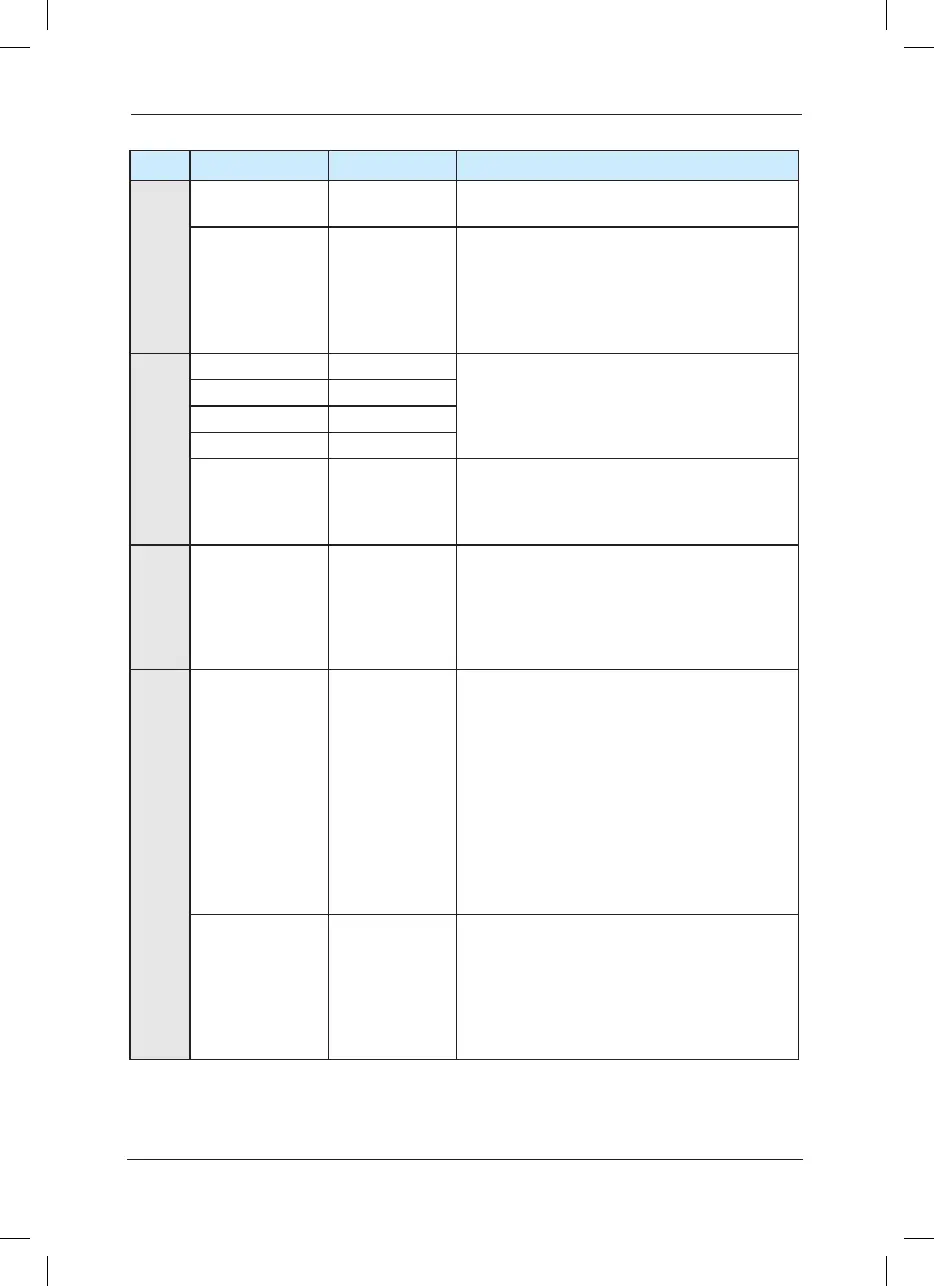
Type Terminal Symbol Terminal Name Function Description
Analog Input
AI1-GND
Analog input
terminal 1
1 Input Voltage range: DC 0V to 10V
2. Input resistance: 100kΩ
AI2-GND
Analog input
terminal 2
1. Input range: DC 0V
~
10V/4mA
~
20mA,
which is determined by J3 jumper on the control
board.
2. Input impedance: It is 100kΩ at the time of
voltage input and 500Ω at the time of current
input.
Digital input
DI1-COM Digital input 1
1. Optical coupling isolation, compatible with
dual polarity input
2. Input resistance: 3.3kΩ
3. Voltage range for level input: 9V
~
30V
DI2-COM Digital input 2
DI3-COM Digital input 3
DI4-COM Digital input 4
DI5-COM
High-speed
pulse input
terminal
In addition to the characteristics of DI1 to DI4, it
can also be used as the high-speed pulse input
channel.
Maximum input frequency is 50kHz.
Analog
Output
AO1-GND Analog output 1
The voltage or current output is determined by
the J4 jumper on the control board.
Output voltage range: 0V
~
10V.
Output current range: 0mA
~
20mA.
Digital output
DO1-CME Digital output 1
Optical coupling isolation, dual polarity open
collector output
Output voltage range:
Output current range:
Caution: The CME and COM is internally
insulated, but they have been short circuited
externally (DO1 is driven by +24V by default
prior to delivery). When DO1 needs to be
driven by the external power, the short circuited
between CME and COM must be disconnected.
FM-COM H i g h - s p e e d
pulse output
It is limited by functional code F5-00 “FM
Terminal Output Mode Selection”.
When it is used as high-speed pulse output, the
maximum frequency can reach 50kHz;
When it is used as open collector output, it is
same as DO1 in terms of specications.
 Loading...
