3 Peripheral Devices and Options
-
117
-
■
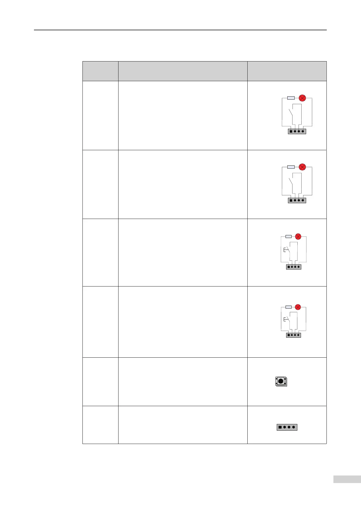
Description of terminals
Input and output terminals of HCB-H
Terminal
Name
Function
Connection between MCTC-
PG and encoder
JP1
Interface for the elevator lock switch
Pins 2 and 3 are for switch input. Pins 1 and 4
are output of the up arrival indicator
(24 VDC output, load capacity: 40 mA).
1 2 3 4
Elevator
Lock input
Up arrival indicator
JP2
Pins 2 and 3 are for switch input. Pins 1 and 4
are output of the down arrival indicator
(24 VDC output, load capacity: 40 mA).
1 2 3 4
Fire
emergency
input
Down arrival indicator
JP3
Interface for the up call button
Pins 2 and 3 are for up call input. Pins 1 and 4
are power supply for the up call indicator
(24 VDC output, load capacity: 40 mA).
1 2 3 4
Up call indicator
Up call
button
JP4
Interface for the down call button
Pins 2 and 3 are for down call input. Pins 1 and
4 are power supply for the down call indicator
(24 VDC output, load capacity: 40 mA).
1 2 3 4
Down call indicator
Down call
button
S1
the address number blinks three times and the
setting is successful.
CN1
Modbus communication and power supply
terminal
Pins 2 and 3 are for Modbus communication.
Pins 1 and 4 are for power supply.
 Loading...