3 Peripheral Devices and Options
-
124
-
Terminal ID Terminal Name Function description Terminal Layout
CN9
+24V/
COM
External 24 VDC
power supply
24 VDC power supply for
the corresponding CANbus
communication module
CAN2+/
CAN2-
CANbus
communication
terminal
CANbus communication between
the GCB and the MCB of elevator 2
in group control
CN8
+24V/
COM
External 24 VDC
power supply
24 VDC power supply for
the corresponding CANbus
communication module
CAN3+/
CAN3-
CANbus
communication
terminal
CANbus communication between
the GCB and the MCB of elevator 3
in group control
CN10
+24V/
COM
External 24 VDC
power supply
24 VDC power supply for
the corresponding CANbus
communication module
CAN4+/
CAN4-
CANbus
communication
terminal
CANbus communication between
the GCB and the MCB of elevator 4
in group control
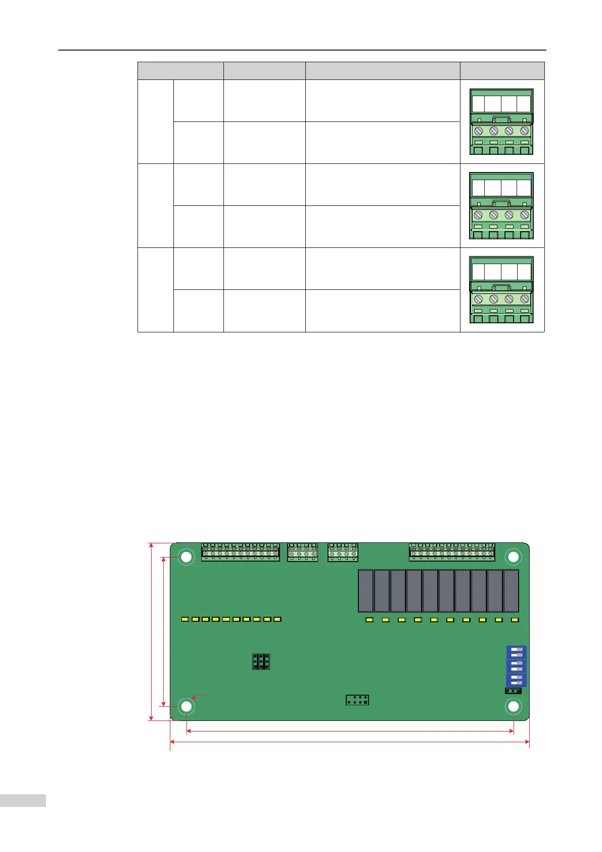
3.3.6 I/O Expansion Board (MCTC-KZ-G1)
The expansion board (MCTC-KZ-G1) has one RS458 interface, one CANbus communi-
cation interface, ten DI and ten DO terminals. The expansion board is connected to the
CAN1 bus of the control board via the CANbus interface to implement I/O terminal ex-
pansion. The CAN1 bus supports up to two expansion boards, one of which is placed
in the equipment room and the other at the top of the car. The DIP switch on the
expansion board is used to set an address. When all switches are OFF, this board is at
the top of the car. When switch 1 is in 1 position, this board is in the equipment room.
The terminals of the expansion board are allocated with functions in FD-11 to 50.
1 Appearance and dimensions
J11
CN1
J5
COM X10
X1
J12 J1
COM MOD+
MOD- M24
X9 X7 X5
X3 X1
X10 X8 X6
X4 X2
Y10 Y9 Y8 Y7
Y6 Y5 Y4 Y3
Y2 Y1
Y10
Y1
COM CAN+
CAN- M24
ON
OFF
OFF
ON
485 CAN
J6
J7 J10
ON OFF
J3
ON
1
2
ON
1
2
ON
1
2
K6
K5
K4
K3
K2
K1
J9
88
74
162
178
Φ3*4
Y6
...
YM1
...
YM2
...
S3
S2
S1
MCTC-KZ-G1
Appearance and dimensions of the MCTC-KZ-G1 (unit: mm)
 Loading...