3 Peripheral Devices and Options
-
132
-
■
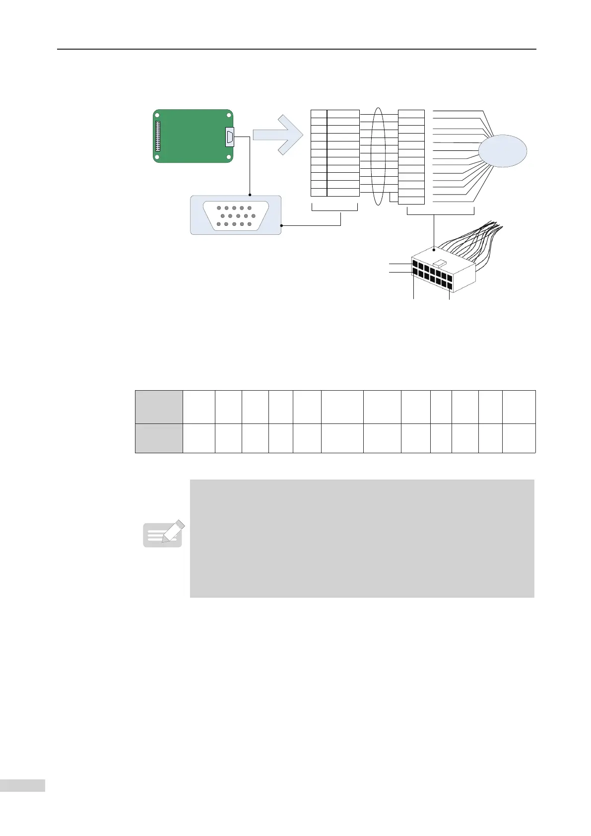
Connection between MCTC-PG-F1 and encoder ERN1313
Encoder
ECN1313
15
610
1115
Top
a
b
6
1
MCTC-PG-F1
PG card
Female 15-way D-type
1
5
6
8
10
11
14
12
15
7
B-
A+
A-
B+
CLK+
CLK-
DATA-
DATA+
5V Sensor
GND
3b
2a
5b
4a
2b
5a
1a
6b
6a
3a
4b
9 5V UP
1b
J1
MCTC-PG-F1
CN1
Connection between the PG card and encoder ERN1313
Signal DATA- A+ GND B+ CLK-
5V
(Sensor)
5V
(UP)
CLK+ B- GND A- DATA+
Encoder
Terminal
1a 2a 3a 4a 5a 6a 1b 2b 3b 4b 5b 6b
Precautions on connecting PG card:
◆
The cable from the PG card to the encoder must be separated from the
cables of the control circuit and the main circuit. Parallel cabling with close
distance is forbidden.
◆
The cable from the PG card to the encoder must be a shielded cable. The
shield must be connected to the PE on the controller side. To minimize
interference, single-end grounding is suggested.
◆
The cable from the MCTC-PG card to the encoder must run through a
separate duct and the metal shell is reliably grounded.
 Loading...