5 System Commissioning
-
162
-
Signal indicator state
Indicator State Description
X1 to X8 input signal indicator ON
There is high level input to the corresponding
input terminals.
B1 to B3 output signal indicator ON The corresponding output terminal has output.
■
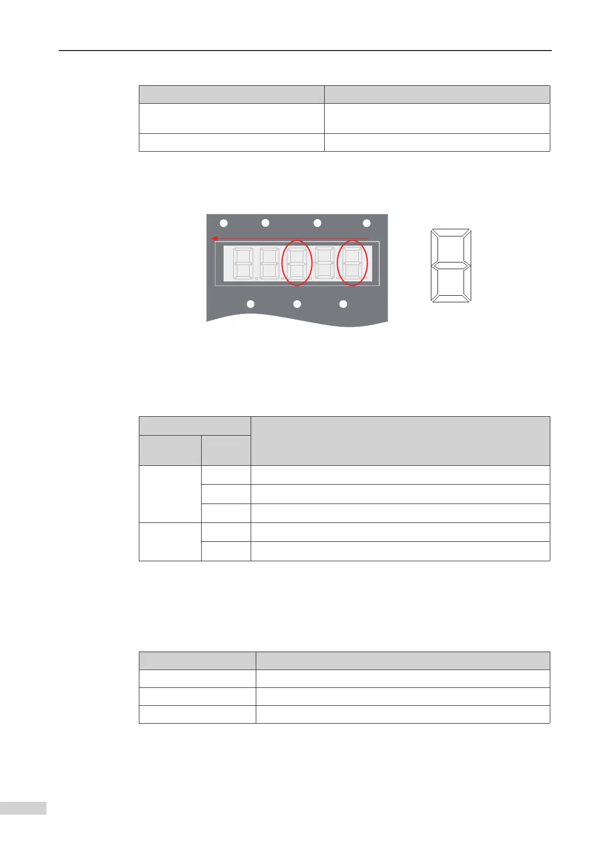
You can view F5-35 on the MCB to see whether the light curtain and door machine
signals are active.
LOCAL/RE
FWD/REV
B
A
E
F
G
C
12345
D
F5-35 monitoring method
F5-35 monitoring description
F-35 LEDs
Indicated Signal
(an lit LED segment indicates the corresponding signal I/O is valid)
No.
Segment
Mark
LED 1
A Door 1 light curtain signal
C Door 1 open limit signal
E Door 1 close limit signal
LED 3
A Door 1 open output
B Door 1 close output
You need to set the NO/NC features of the CTB input signals in F5-25 and ensure that
the setting is consistent with the NO/NC feature of the actual electrical switches (light
curtain and door open/close limit switches). CTB control can be implemented only af-
ter you perform the setting correctly. If the NO/NC feature setting is inconsistent with
the actual conditions, the door cannot open or close properly or fault E53 is reported.
Bit of F5-25 CTB Input Signal
Bit0 Used to set NO/NC feature of door 1 light curtain signal
Bit2 Used to set NO/NC feature of door 1 open limit signal
Bit4 Used to set NO/NC feature of door 1 close limit signal
 Loading...