9 Description of Functions and Schemes
-
339
-
2) Electrical implementation scheme
In case of power failure, this function can be implemented by using the 12 V power
supply of the intercom system or electric brake release device to supply power to the
MCB.
■
As 12 V input in case of power failure, 12 V and MCM terminals are added on the
MCB to supply power to the PG card encoder so as to provide direction and speed
feedback during emergency evacuation by shorting stator braking.
■
CDS (equipment-roomless control cabinet door switch) is added. When the cabinet
door is open, the switch contact is ON and 12 V is supplied to terminal CN3.
■
long-term connection of 12 V to the system in case of power failure.
■
12 V and 24 V require common ground connection.
CN3
M24V
MOD1+
CAN1+
CAN1-
MOD1-
MCM
+12V
MCM
T01
B01
Intercom
emergency power
supply
CDS
+24V
GND
NICE3000
new
controller
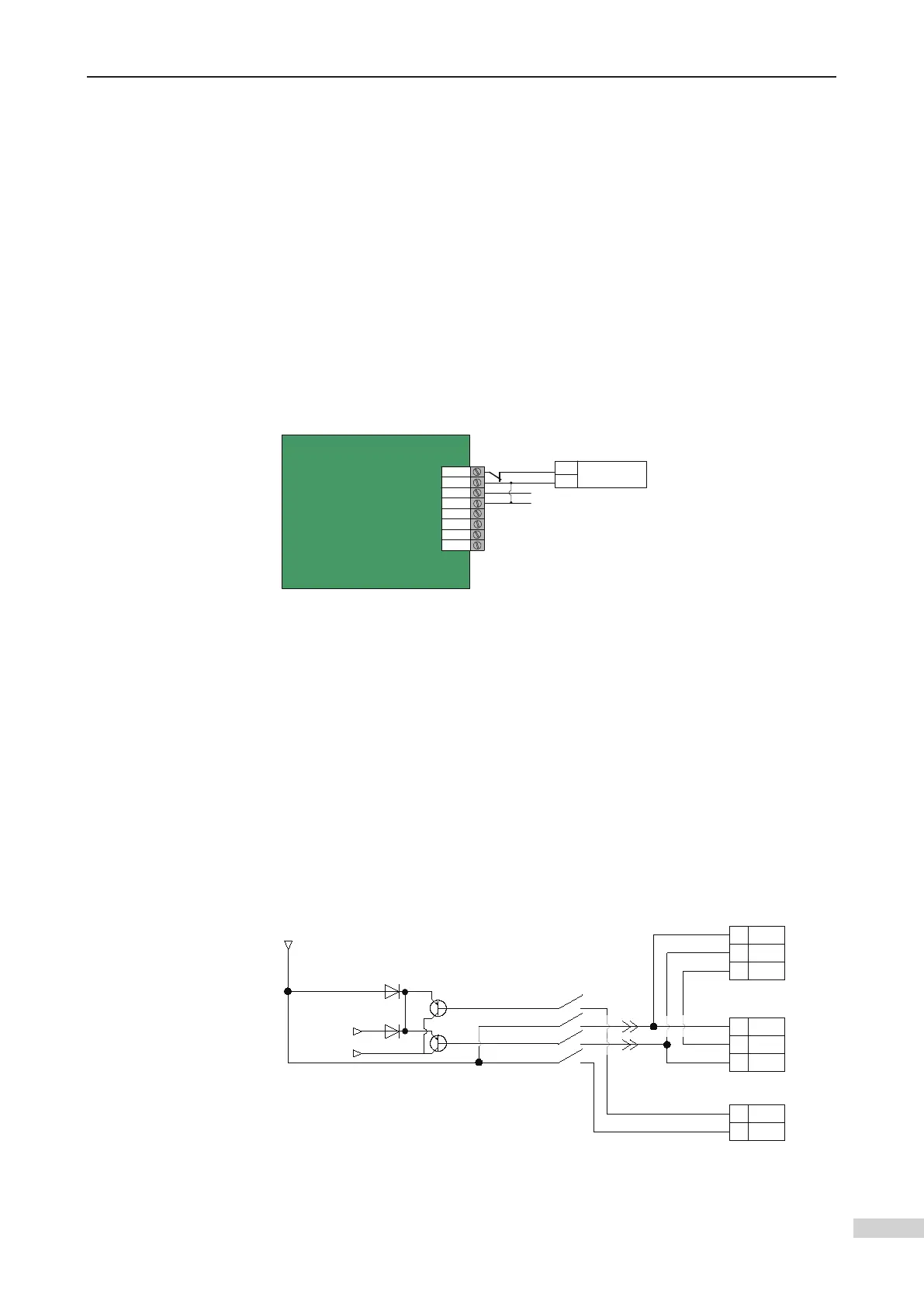
12 V input is added on the up and down leveling optoelectronic signal and power
supply side. The 12 V power supply comes from the intercom emergency lighting.
The action of the optoelectronic switch is driven by the emergency light upon power
failure.
■
SGD31 optoelectronic switches satisfy this condition).
■
The 9 V voltage terminal X of the new hardware version of the MCB can identify that
signals are active.
■
A 1N4007 diode with 1 A rated current and 1000 V reverse breakdown voltage must
be used for mutual separation on the optoelectronic power supply side.
X3
X2
X1
MCB
3
2
1
GND
Up leveling signal
Down door zone signal
SX1
FL2
FL1
SCB
6
4
3
Up door zone signal
X10
X9
CTB
2
1
Down leveling signal
AB:7
AB:10
24
VDC
12
VDC
DZU
DZU
D1
D2
 Loading...