2 Installation and Wiring
-
61
-
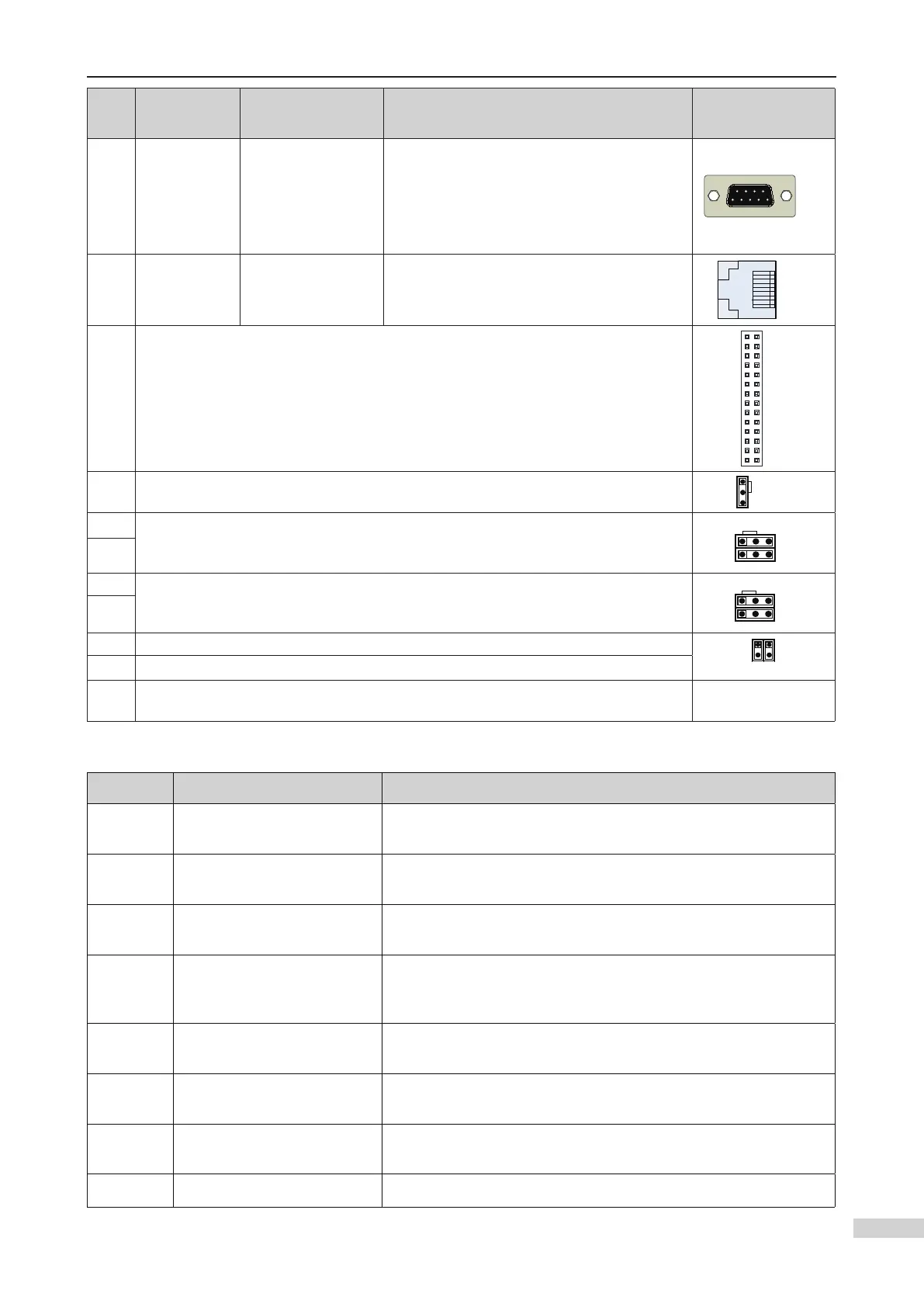
No. Code Terminal Name Function description
Terminal
Arrangement
CN5 DB9 interface
RS232
communication
interface
Interface for:
Site commissioning software
Residential monitoring
RS232/RS485 parallel/group control
Software downloading of the MCB and DSP
board
CN5
CN12 RJ45 interface
Operation panel
interface
Used to connect the operation panel
CN12
J12 Interface for connecting the PG card
J12
J1
Factory reserved, optional grounding terminal for AI. The pins marked with “COM”
are not connected to the ground by default.
J1
J5
Factory reserved, termination resistor connection terminal for the MOD2
communication control board. The pins marked with “ON” are connected to the
termination resistor by default.
J5
J6
J6
J13 Factory reserved, termination resistor connection terminal for the CAN2
communication control board. The pins marked with “ON” are connected to the
termination resistor by default.
J14
J13
J14
J7 Factory reserved, internal 24 V PE terminal, shorted by default
J8J7
J8 Factory reserved, external 24 V PE terminal, shorted by default
J9/J10
Factory reserved. Do not short them randomly. Otherwise, the controller may not
work properly.
Description of indicators on the MCB
No. Terminal Name Function description
MOD2
Modbus2 communication
indicator
When communication with Internet of Things and MIB/remote
monitoring board is normal, this indicator is on (green).
COP
CAN1 communication
indicator
When communication between the MCB and the CTB is normal,
this indicator is on (green).
HOP
Modbus1 communication
indicator
When communication between the MCB and the HCB is normal,
this indicator is on (green).
CAN2
Group control
communication indicator
This indicator is steady on (green) when communication for
parallel/group control is normal, and blinks when the running in
parallel/group control mode is normal.
232
Serial communication
indicator
This indicator is on (green) when communication with the host
computer or MIB/remote monitoring board is normal.
X1 to X24
Low voltage input signal
indicator
This indicator is on when the external input is active.
X5 to X28
High voltage input signal
indicator
This indicator is on when the external input is active.
Y1 to Y6 Output signal indicator This indicator is on when the system output is active.
 Loading...