35
Frame
Product Support: www.instron.com
The controlling software is equipped with overload protection for the load transducer. The
overload protection should prevent damage to the load transducer during a test by shutting
off the HPS when an overload condition occurs.
Position measurement
A position encoder is used to determine the position of the piston inside the hydraulic cylinder. For
specifications, refer to information provided in the System Operating Instructions (supplied separately).
All encoders are digital quadrature style encoders.
DX-300 models use a string-type encoder (see Figure 14). The encoder is mounted to either the bottom
of the base plate or lower crosshead depending on frame model. Piston movement is transferred to the
encoder by a guide rod that is attached to either the bottom of the compression table or piston
(depending on frame model) and extends through the base plate. The encoder string is attached to the
bottom of the guide rod. As the piston and compression table move up and down, the guide rod also
moves and actuates the encoder string which produces an electrical signal in the encoder. The electrical
signal is transmitted to the 59 Series control unit. The 59 Series control unit converts the signal into the
relative position of the loading unit in relation to a stationary frame member.
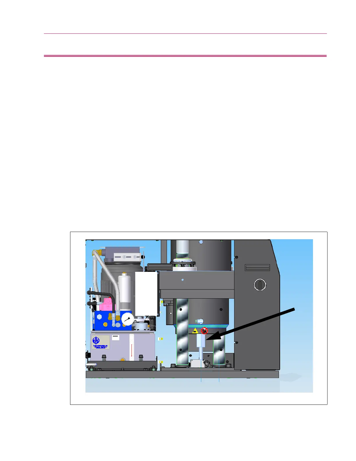
DX-600 models use a Micropulse Linear transducer. (see Figure 15). The encoder is mounted to the
bottom of the cylinder. The Micropulse absolute quadrature output linear transducer is a
magnetostrictive linear displacement transducer that provides electrical output signals in ABZ quadrature
format. The electrical signal is transmitted to the 59 Series control unit. The 59 Series control unit
converts the signal into the relative position of the loading unit in relation to a stationary frame member.
Figure 15. Location of position encoder on 600 DX
 Loading...


