27
Frame
Product Support: www.instron.com
Grip assemblies
Grip assemblies are provided on frames with either G1-style or G7-style crossheads; they are not provided
on frames with G8-style crossheads. Both the tension and adjustable crossheads are equipped with grip
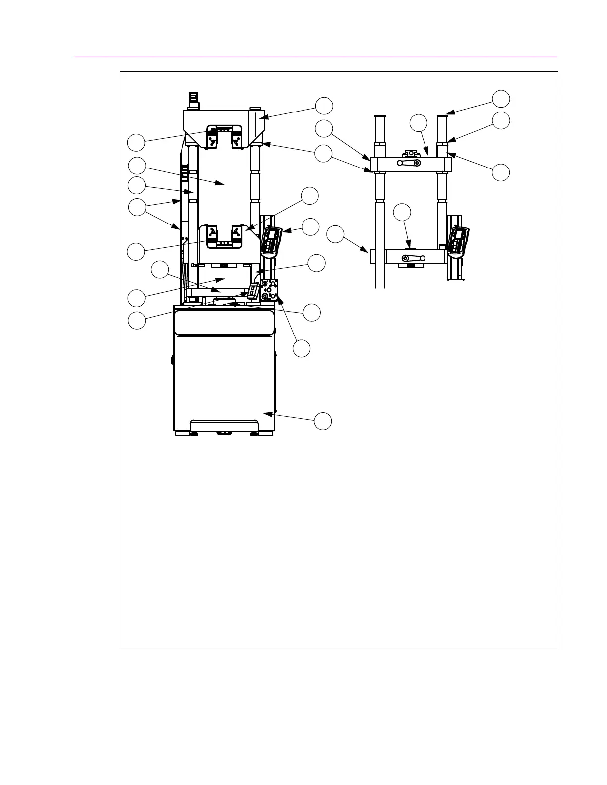
Figure 9. DX frame components.
1. Grip assembly*
2. Tension test space*
3. Notched column*
4. Flexible track*
5. Compression test space
6. Hydraulic grip controls (frames with
G7-style crossheads only)
7. Tension crosshead*
a. G7-style
b. G1-style
8. Collar*
9. Column cap or bolt
10. Spacer (not used on all models)
11. Lower retaining ring*
12. Adjustable crosshead
a. G7-style
b. G1-style
c. G8-style (Not shown. Similar to
G1-style but with no grip pocket or grip
assembly components.)
13. User control panel
14. Screw column
15. Compression table
16. Load cell
17. HPS controls
18. Base
* These items provided on frames with
G1-style or G7-style crossheads only.
7a
7b
11
13
14
15
16
17
18
1
1
10
8
9
1
2
3
4
1
5
6
12a
12b
 Loading...


