Chapter 3: Additional System Details
26 M47-17028-EN
tension fixtures can be mounted to the tension crosshead with proper adapters. This is typically done by
either clamping the adapter in the grip assemblies or by using the bolt pattern provided on the bottom of
the crosshead to bolt the adapter (or fixture) to the crosshead. Some adapters may mount to the
crosshead using the bolt pattern on the top of the crosshead. For more information on the bolt patterns,
refer to information provided in the System Operating Instructions (supplied separately).
The tension crosshead (8a or 8b, Figure 9) is mounted to two notched columns (3) and is part of the
loading unit. The position of the tension crosshead can be adjusted when it is necessary to change the
height of the tension test opening. The crosshead can be placed at any of the available notches in the
notched columns. Crosshead adjustment is only done between tests, never during a test. For procedures
on adjusting the crosshead, refer to information provided in the System Operating Instructions (supplied
separately).
Adjustable crosshead
For frames equipped with either G1-style or G7-style crossheads, the adjustable crosshead is equipped
with grip assemblies for tension testing and a bumper plate on the bottom of the crosshead for
attachment of compression accessories. For frames equipped with G8-style crossheads, the adjustable
crosshead is only equipped with a bumper plate on the bottom of the crosshead for attachment of
compression accessories. For more information on the grip assemblies, refer to information provided in
the System Operating Instructions (supplied separately).
The adjustable crosshead is mounted to two screw columns and is part of the fixed unit. The position of
the adjustable crosshead can be adjusted when it is necessary to change the height of either the tension
test opening or compression test opening. A hydraulic motor is used to adjust the position of the
adjustable crosshead. The operator controls the hydraulic motor through a control switch on the front of
the frame base. Crosshead adjustment is only done between tests, never during a test. For more
information on adjusting the position of the adjustable crosshead, refer to information provided in the
System Operating Instructions (supplied separately).
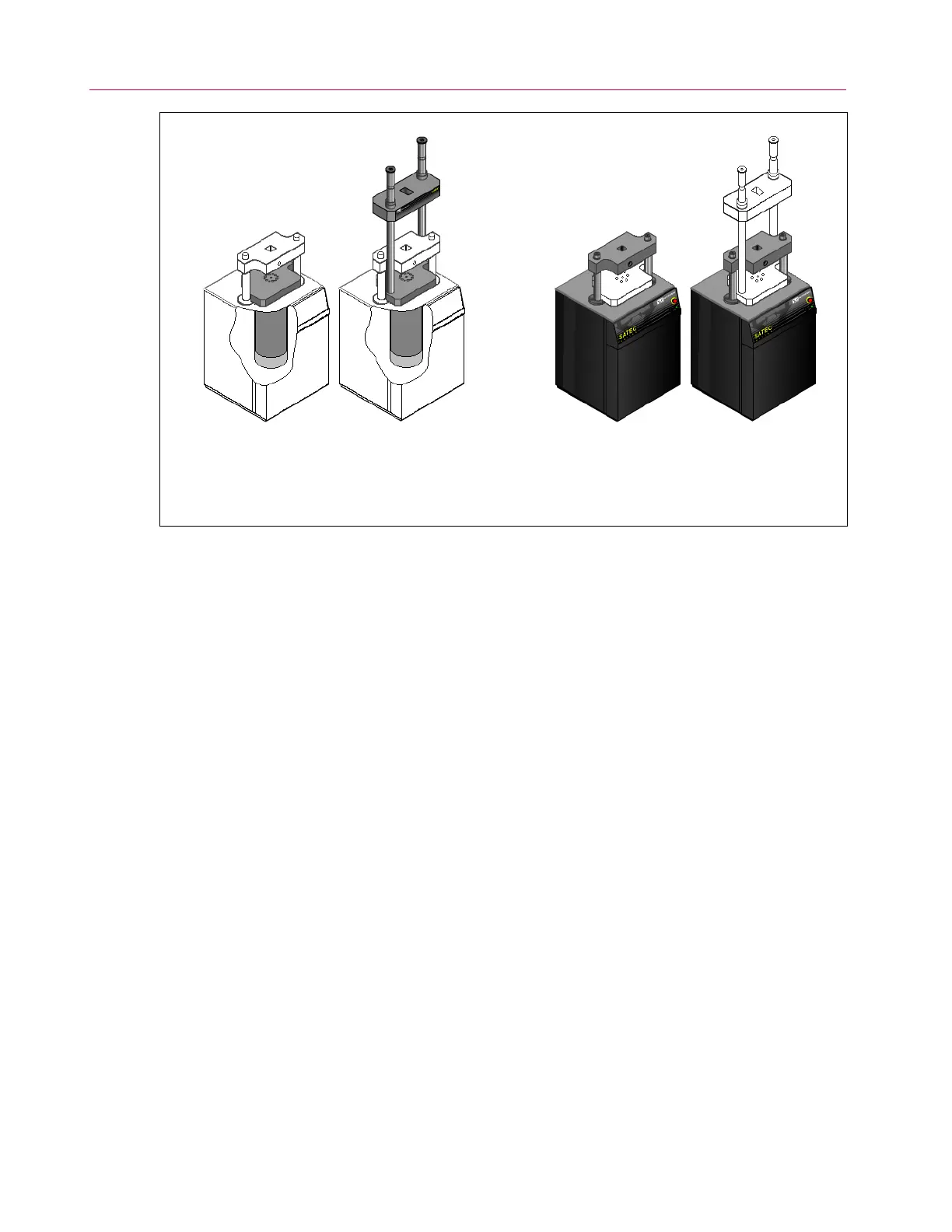
Figure 8. The loading unit and the fixed unit.
Loading Unit Components:
• Tension Crosshead*
• Notched Columns*
• Compression Table
• Hydraulic Cylinder
Fixed Unit Components:
• Adjustable Crosshead
• Screw Columns
• Base
G8-Style
Crossheads
G1-Style or G7-Style
Crossheads
G8-Style
Crossheads
G1-Style or G7-Style
Crossheads
* These items provided on frames with G1-style or G7-style crossheads only.
 Loading...


