53
Replacement or repair of load cells
Product Support: www.instron.com
7. Once work is complete, replace all covers.
Replacement or repair of load cells
Instron load cells, in general, are electrically calibrated, self-identifying and rationalized. Approximate
resistances can be provided to allow confirmation of a possible broken gauge, or a faulty connector or
cable.
If a strain gauge in a cell has been badly overstressed, but still maintains its electrical continuity, the cell
may show a higher than normal amount of creep. If a gauge has become improperly bonded due to
degradation in use, the cell may exhibit a combination of general instability in its balance point, together
with a large amount of creep. Difficulties of this sort rarely appear as an instability in the calibration of
the cell.
If a load cell has been overloaded, the load-sensitive member may be permanently deformed to the extent
that the proper dimensional alignments inside the cell are no longer maintained. If you suspect that a cell
may be damaged, contact your local Instron Services department as directed on page 13 to arrange
returning the load cell for analysis and possible repair.
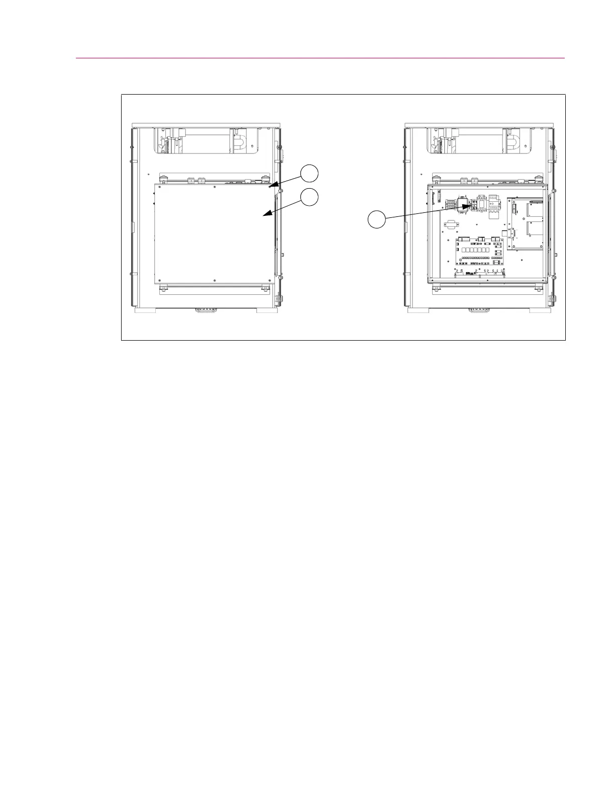
Figure 20. Accessing and locating the fuses.
1. M5 button head
cap screw
2. Inside cover
3. Power supply fuses
View A: Front cover removed View B: Inside cover removed
1
2
3
 Loading...


