Intel Desktop Board DG965MQ Product Guide
18
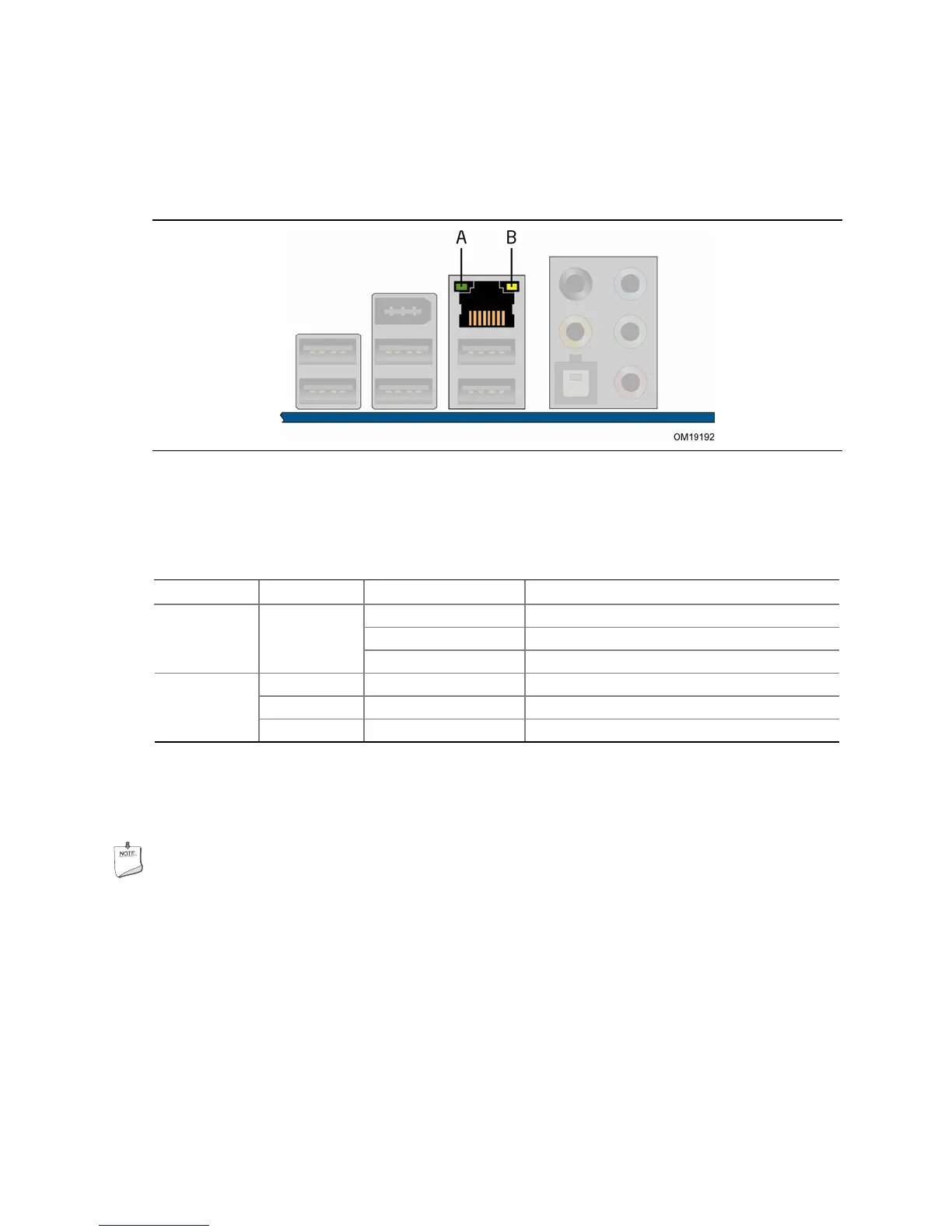
RJ-45 LAN Connector LEDs
Two LEDs are built into the RJ-45 LAN connector located on the back panel (see
Figure 2). These LEDs indicate the status of the LAN.
Figure 2. LAN Connector LEDs
Table 4 describes the LED states when the board is powered up and the LAN
subsystem is operating.
Table 4. LAN Connector LED States
LED LED Color LED State Indicates
Off LAN link is not established
On LAN link is established
A Green
Blinking LAN activity is occurring
N/A Off 10 Mb/s data rate
Green On 100 Mb/s data rate
B
Yellow On 1000 Mb/s data rate
Hi-Speed USB 2.0 Support
NOTE
Computer systems that have an unshielded cable attached to a USB port might not
meet FCC Class B requirements, even if no device or a low-speed USB device is
attached to the cable. Use a shielded cable that meets the requirements for a
full-speed USB device.
The desktop board supports up to 10 USB 2.0 ports via ICH8 six ports routed to the
back panel and four ports routed to two internal USB 2.0 headers. USB 2.0 ports are
backward compatible with USB 1.1 devices. USB 1.1 devices will function normally at
USB 1.1 speeds.