Installing and Replacing Desktop Board Components
51
Connecting to the Parallel Port Header
See Figure 25, G for the location of the parallel port header. Table 11 shows the pin
assignments for the header.
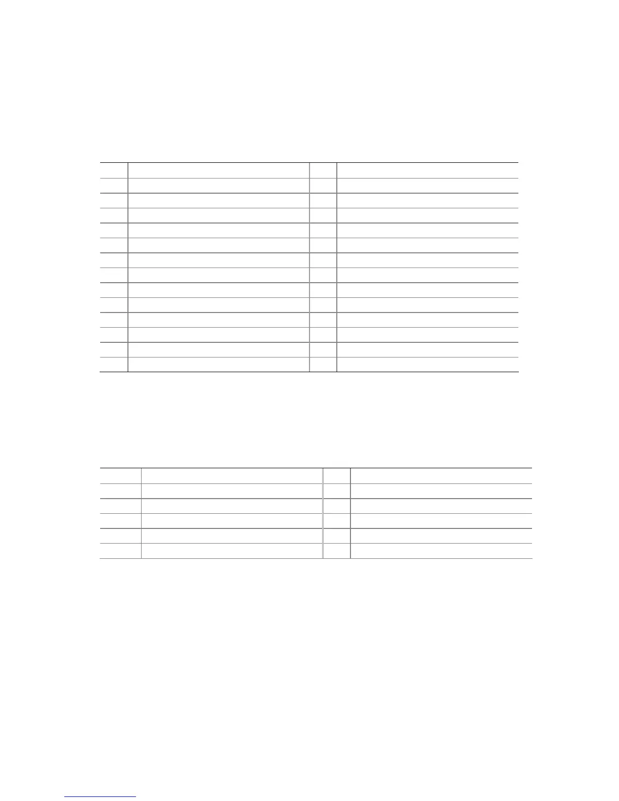
Table 11. Parallel Port Header Signal Names
Pin Signal Name Pin
Signal Name
1 STROBE# 2 AUTOFD#
3 PD0 4 FAULT#
5 PD1 6 INIT#
7 PD2 8 SLCTIN#
9 PD3 10 Ground
11 PD4 12 Ground
13 PD5 14 Ground
15 PD6 16 Ground
17 PD7 18 Ground
19 ACK# 20 Ground
21 BUSY 22 Ground
23 PERROR 24 Ground
25 SELECT 26 Key (no pin)
Connecting to the Serial Port Header
See Figure 25, D for the location of the serial port header. Table 12 shows the pin
assignments for the header.
Table 12. Serial Port Header Signal Names
Pin Signal Name Pin
Signal Name
1 DCD 2 RXD#
3 TXD# 4 DTR
5 Ground 6 DSR
7 RTS 8 CTS
9 RI 10 No connection
 Loading...