Intel Desktop Board DH61AG Technical Product Specification
60
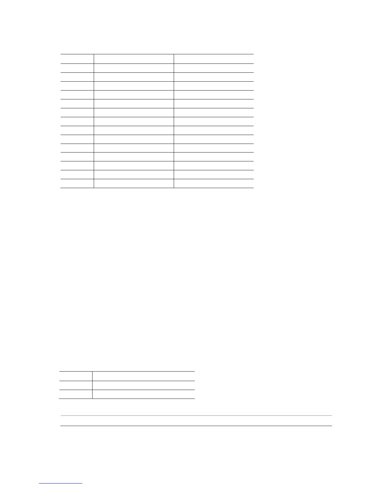
Table 34. PCI Express Full-/Half-Mini Card Connector (continued)
Pin Signal Name Additional Signal Name
39 +3.3 Vaux
40 GND
41 +3.3 Vaux
42 LED_WWAN#
43 Reserved
44 LED_WLAN#
45 Reserved (mSATA) Vendor
46 LED_WPAN#
47 Reserved (mSATA) Vendor
48 +1.5V
49 Reserved (mSATA) DA/DSS
50 GND
51 Reserved (mSATA) Presence Detection
52 +3.3V
2.2.3.2 Add-in Card Connectors
The board has the following add-in card connectors:
• One PCI Express 2.0 x4 connector. The x4 interface supports simultaneous
transfer speeds up to 500 MB/s of peak bandwidth per lane, per direction, for up to
4 GB/s concurrent and bi-directional bandwidth.
• One PCI Express Half-Mini Card slot
• One PCI Express Full-/Half-Mini Card slot (removable stand-offs in full-length keep
out zone allows repurposing of Full-Mini Card slot into Half-Mini Card slot)
2.2.3.3 Power Supply Connectors
The board has the following power supply connectors:
• External Power Supply – the board can be powered through a 19 V DC
connector on the backpanel. The backpanel DC connector is compatible with a 7.4
mm/OD (outer diameter) and 5.1 mm/ID (inner diameter) plug, where the inner
contact is +19 (±10%) V DC and the shell is GND. The maximum current rating is
12 A.
• Internal Power Supply – the board can alternatively be powered via the internal
19 V DC 1 x 2 power connector, where pin 1 is GND and pin 2 is +19 (±10%) VDC.
Table 35. 19 V Internal Power Supply Connector
Pin Signal Name
1 Ground
2 +19 V (±10%)
For information about Refer to
Power supply considerations Section 2.6.1, page 71