Intel Desktop Board DH61AG Technical Product Specification
64
2.2.3.6 Debug Header
During the POST, the BIOS generates diagnostic progress codes (POST codes) to I/O
port 80h. If the POST fails, execution stops and the last POST code generated is left
at port 80h. This code is useful for determining the point where an error occurred.
Displaying the POST codes requires a POST card that can interface with the Debug
header. The POST card can decode the port and display the contents on a medium
such as a seven-segment display.
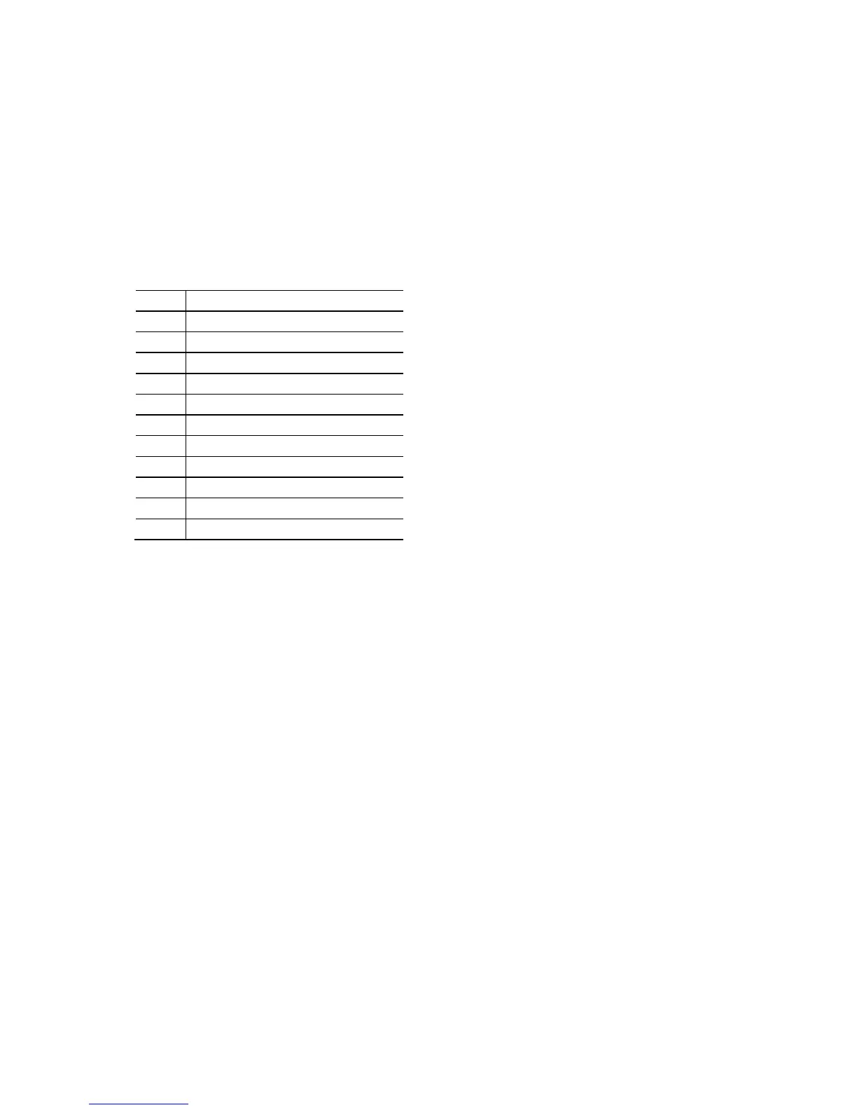
Table 38. Debug Header
Pin Signal Name
1 VCC3
2 VCC3
3 PLTRST#
4 LPC_CLK
5 LAD0/FWH0
6 LAD1/FWH1
7 LAD2/FWH2
8 LAD3/FWH3
9 LFRAME/FWH4#
10 GND
11 GND
2.3 I/O Shields
Two I/O shields are provided with the board:
• Half-height I/O shield
• Standard-height I/O shield
The half-height I/O shield allows access to all back panel connectors while being
specifically designed for thin mini-ITX chassis, compliant with version 2.0 of the Mini-
ITX Addendum to the microATX Motherboard Interface Specification. As an added
benefit for system configurations with an internal TV tuner in the PCI Express Mini
Card form factor, the I/O shield also provides a pre-cut hole for user installation of an
F-type external antenna connector.
The standard-height I/O shield provides access to all the same connectors as the half-
height I/O shield while being compatible with standard mini-ITX and microATX chassis.
In addition to the F-type pre-cut hole, the standard-height I/O shield also provides
pre-cut holes for user installation of two external wireless antennas for system
configurations with wireless PCI Express Mini Card solutions.
Figure 18 and Figure 19 are I/O shield reference diagrams.