Intel® Server S2600WF Product Family Configuration Guide
101
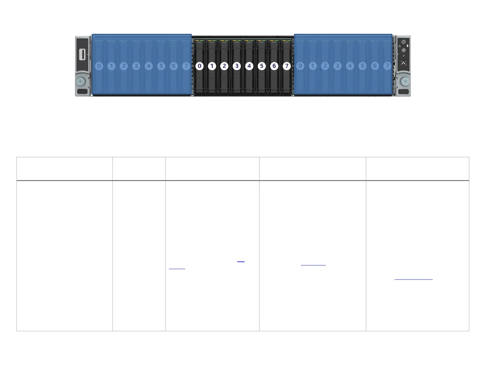
4.7.2 2U - 8x2.5” Drive Bay Module #2 – Cable Guide (with no SAS Expander)
4.7.2.1 Drive Bay Module #2 - SAS/SATA Cable Guide
The following table identifies the appropriate SATA/SAS data cable kit(s) necessary to route data signals from Onboard SATA ports or available SAS
RAID mezzanine and PCIe add-in options to the 8x2.5” backplane installed to Drive Bay Module #2.
Table 61. Drive bay module #2 SAS/SATA cable guide
Onboard Multi-port SATA Ports
Mezzanine 12 Gb SAS ROC Module to
12 Gb SAS RAID PCIe* add-in card to
Drive Bay #2
(no SAS Expander)
R2208WF…+ 8 drive option
R2224WF…
8 x 2.5”
SATA – All Drives
SAS – All Drives
SATA 0-3
BP 0-3
730mm HD -- HD
SATA 4-7
BP 4-7
875mm HD -- HD
From data above, select
appropriate cable kits from list
below:
AXXCBL730HDHD
(1) 730mm Included in all 2.5” L6
AXXCBL875HDHD
(1) 875mm Included in R2224 L6
SAS Mezz
BP 0-3
730mm HD -- HD
SAS Mezz
BP 4-7
875mm HD -- HD
From data above, select appropriate
cable kits from list below:
AXXCBL730HDHD
(1) 730mm Included in all 2.5” L6
AXXCBL875HDHD
(1) 875mm Included in R2224 L6
SAS PCIe
BP 0-3
1
650 or 730mm HD -- HD
SAS PCIe
BP 4-7
1
730 or 800mm HD -- HD
From Riser #2:
SAS PCIe
BP 0-3
1
800 or 875mm HD -- HD
SAS PCIe
BP 4-7
1
730 or 875mm HD -- HD
From data above, select appropriate
cable kits from list below:
AXXCBL650HDHD
AXXCBL730HDHD
(2) 730mm Included in all 2.5” L6
AXXCBL800HDHD
AXXCBL875HDHD
(4) 875mm Included in R2224 L6
1
1 or 2 cable lengths may be specified for a PCIe add-in card. Generally, if the cable connector of the add-in card is located on the back edge of the card, a shorter cable is specified.
Cable connectors on the top edge or near the front of the add-in card will require the longer cable length.
Drive Bay #2

 Loading...


