Intel® Server S2600WF Product Family Configuration Guide
33
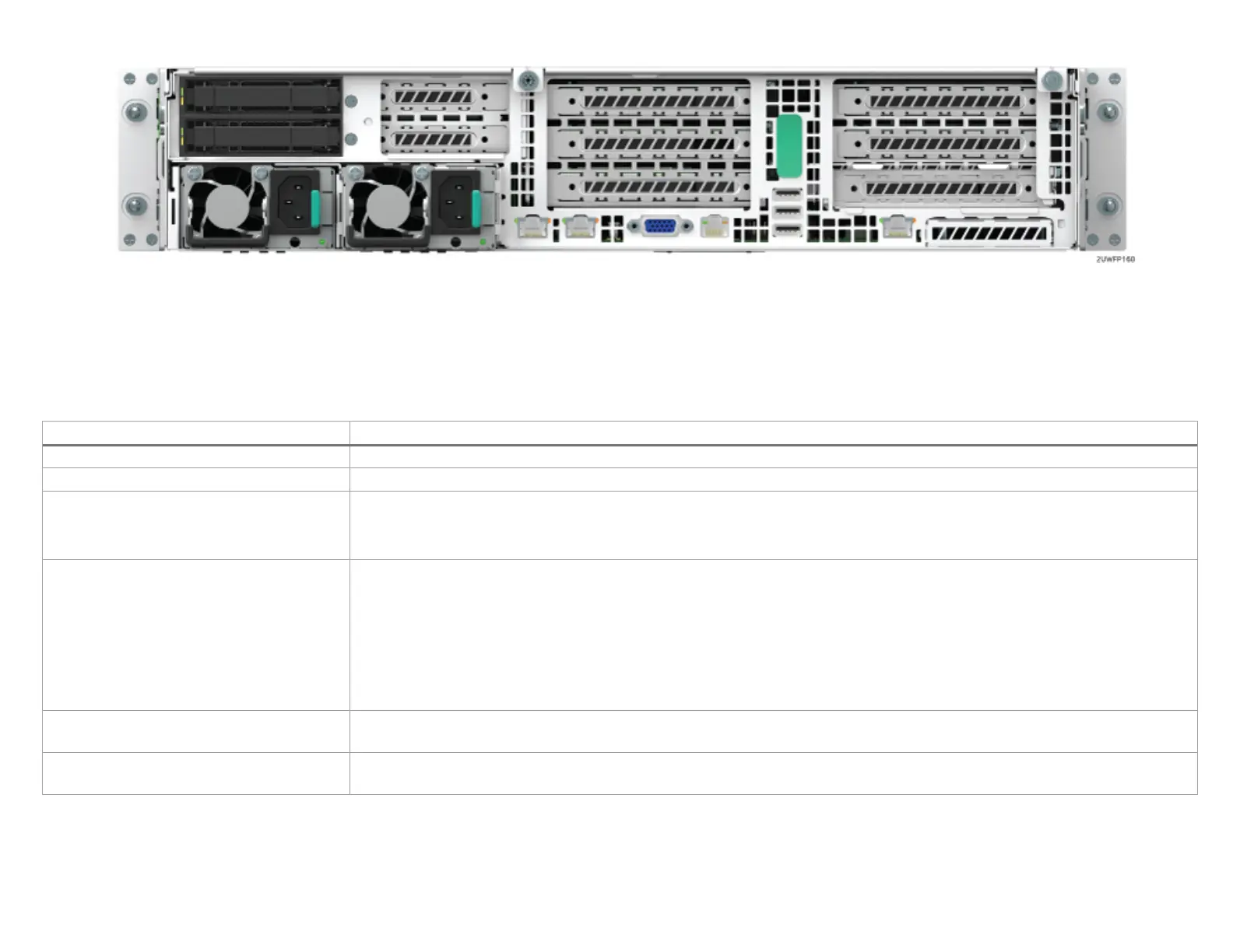
Figure 16. 2U System back panel with optional 2 x 2.5” hot swap drive bay
Table 8 describes the features of the 2U server system configurations. Storage system configurations include R2312WFxxxx and R2224WFxxxx. Non-
storage system configurations include R2308WFxxxx, R2208WFxxxx, and R2208WFxxxx +8 (base 8 drive system with 8 drive add in module).
Table 8. Intel® Server System R2000WF product family features
Intel® Server Board S2600WF product family
Maximum Supported Processor Thermal
Design Power (TDP)
Note: Intel® Server Systems in this family may support a lower maximum Thermal Design Power (TDP). See the appropriate Intel®
System TPS for maximum supported TDP.
o Front and back (non-storage system configurations only)
• RJ-45 serial port A connector
• Dual RJ-45 network interface connectors (S2600WFT-based systems only)
• Dedicated RJ-45 server management NIC
• (3) – USB 3.0 connectors on back panel
• (2) – USB 3.0 connectors on front panel (non-storage system configurations only)
•
(1) – USB 2.0 connector on rack handle (storage configurations only)
Internal I/O Connectors/Headers
• (1) – Type-A USB 2.0 connector
• (1) – DH-10 serial port B connector
• (6) – managed 60 mm hot swap capable system fans
• Integrated fans included with each installed power supply module

 Loading...


