On-board Connector/Header Overview Intel® Server Board S2600CO Family TPS
Revision 1.0
Intel order number G42278-002
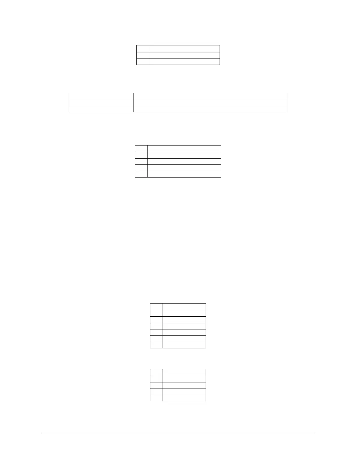
Table 45. Chassis Intrusion Header Pin-out (CHAS INTR)
Table 46. Chassis Instrusion Header State Description
IBMC CHASSIS_N is pulled HIGH. Chassis cover is closed.
IBMC CHASSIS_N is pulled LOW. Chassis cover is removed.
8.4.6 IPMB Connector
Table 47. IPMB Connector Pin-out (IPMB)
8.5 Fan Connectors
The server board provides support for nine fans. Seven of them are system cooling fans; two of
them are CPU fans.
8.5.1 System FAN Connectors
The server board provides support for seven system cooling fans. Each connector is monitored
and controlled by on-board platform management. On the server board, each system fan
connector is labeled SYS_FAN_#, where # = 1 thru 7. The six system cooling fan connectors
near the front edge of the board (SYS_FAN_1 to SYS_FAN_6 are 6-Pin connectors; the one
system cooling fan near rear edge of the board is a 4-Pin connectors (SYS_FAN_7). Following
table provides the pin-out for all system fan connectors.
Table 48. 6-pin System FAN Connector Pin-out (SYS_FAN_1 to SYS_FAN_6)
Table 49. 4-pin System FAN Connector Pin-out (SYS_FAN_7)

 Loading...


