6 Intel
®
Server Board S5000PSL
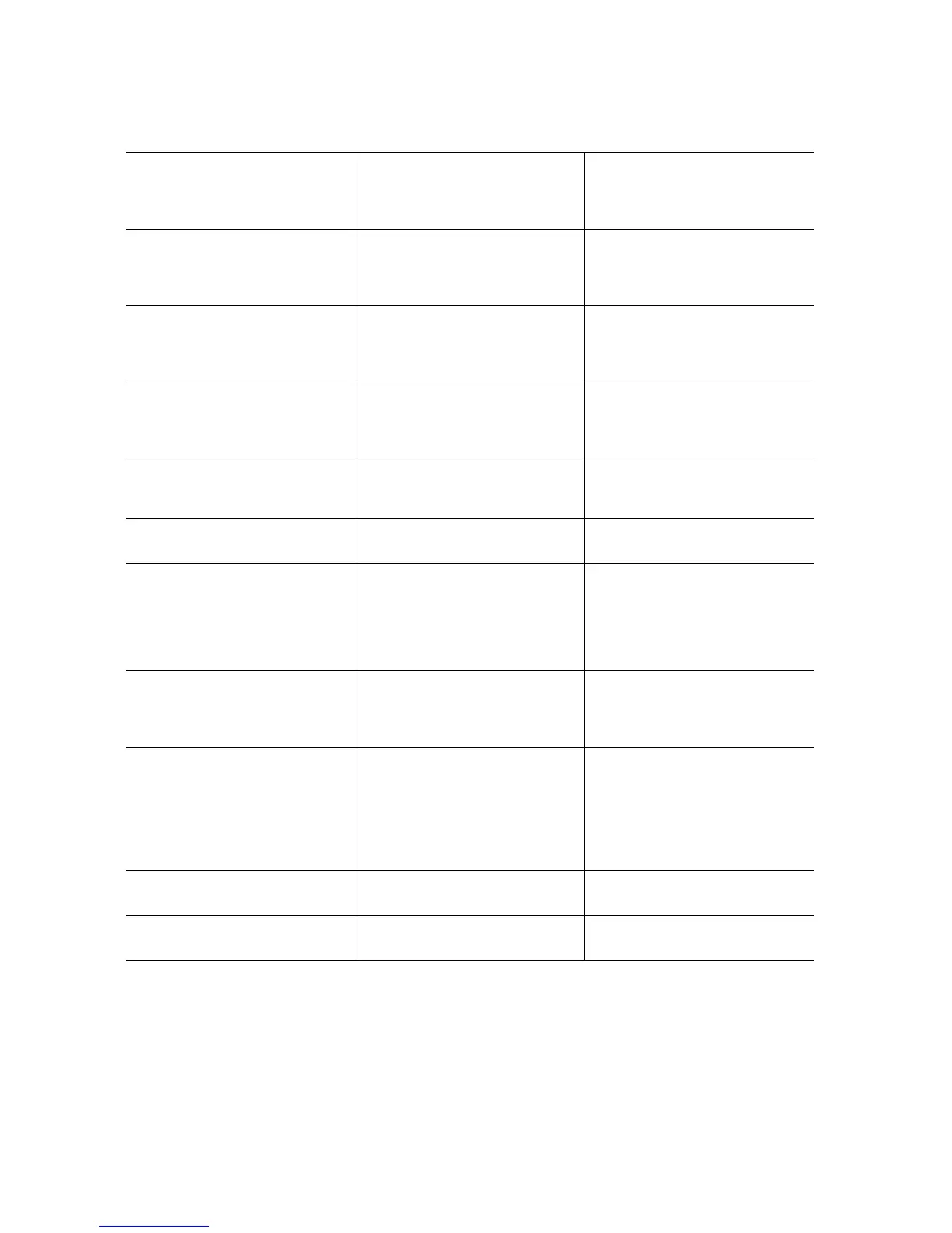
Figure 2. Server Board Connector and Component Locations
F. PCI Express x8 slot 5 V. System fan 4 header KK. SATA 2 or SAS 0 (SAS 0 is
available only on product
codes S5000PSLSAS and
S5000PSLSASR)
G. PCI Express x8 slot 6 W. System fan 3 header LL. SATA 3 or SAS 1 (SAS 1 is
available only on product
codes S5000PSLSAS and
S5000PSLSASR)
H. CMOS battery X. IPMB connector MM. SATA 4 or SAS 2 (SAS 2 is
available only on product
codes S5000PSLSAS, and
S5000PSLSASR)
I. P12V4 connector Y. System fan 2 header NN. SATA 5 or SAS 3 (SAS 3 is
available only on product
codes S5000PSLSAS and
S5000PSLSASR)
J. RMM connector (connector
for Intel
®
Remote
Management Module)
Z. System fan 1 header OO. USB port
K. Back panel I/O ports (see
Figure 4 on page 12)
AA. Processor power connector PP. Front control panel header
L. Diagnostic and Identify
LEDs (see Figure 4 on
page 12)
BB. USB header QQ. SATA_Key: SATA RAID 5
key connector (product
codes S5000PSLSATA,
S5000PSLSATAR,
S5000PSLROMB, and
S5000PSLROMBR only)
M. System fan 6 header CC. IDE connector RR. SAS_Key: SAS RAID 5 key
connector (product codes
S5000PSLSAS and
S5000PSLSASR only)
N. System fan 5 header DD. Enclosure management
SATA SGPIO header
(product codes
S5000SLSATA,
S5000SLSATAR,
S5000PSLROMB, and
S5000PSLROMBR)
SS. Serial B / emergency
management port header
O. Main power connector EE. Intel
®
Local Control Panel
header
TT. Chassis intrusion header
P. Auxiliary power signal
connector

 Loading...


