Intel® Xeon™ Processor with 800 MHz System Bus
Datasheet 69
NOTES:
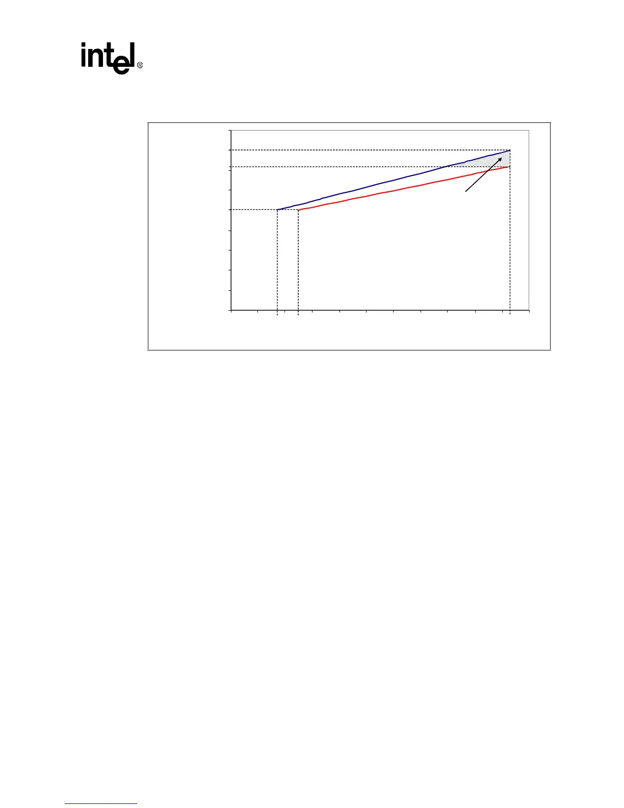
1. Thermal Profile A is representative of a volumetrically unconstrained platform. Please refer to Table 24 for
discrete points that constitute the thermal profile.
2. Implementation of Thermal Profile A should result in virtually no TCC activation. Furthermore, usage of
thermal solutions that do not meet processor Thermal Profile A will result in increased probability of TCC
activation and may incur measurable performance loss. (See Section 6.2 for details on TCC activation).
3. Thermal Profile B is representative of a volumetrically constrained platform. Please refer to Table 25 for
discrete points that constitute the thermal profile.
4. Implementation of Thermal Profile B will result in increased probability of TCC activation and may incur
measurable performance loss. Furthermore, usage of thermal solutions that do not meet Thermal Profile B
do not meet the processor’s thermal specifications and may result in permanent damage to the processor.
5. Refer to the Intel® Xeon™ Processor with 800 MHz System Bus Thermal/Mechanical Design Guidelines for
system and environmental implementation details.
Figure 13. Intel® Xeon™ Processor with 800 MHz System Bus Thermal Profiles A and B
0
10
20
30
40
50
60
70
80
0 102030405060708090100110
Po wer
W
Tcase [°C]
Thermal Profile A
Y = 0.28 * x + 43
TDP
T
CASE MAX_B
@
TDP
T
CASE_MAX
@
Pcontrol_base
T
CASE_MAX_A
@
TDP
Thermal Profile B
Y = 0.35 * x + 44
P
CONTROL_ BASE_B
T
CASE_MAX_B
is a thermal
solution design point. In
actualit y, units will not
exceed T
CASE_MAX_A
due
to TCC activation.
P
CONTROL_B ASE_ A

 Loading...


