Intel® Xeon™ Processor with 800 MHz System Bus
28 Datasheet
NOTES:
1. V
OS
is measured overshoot voltage.
2. T
OS
is measured time duration above VID.
2.11.3 Die Voltage Validation
Overshoot events from application testing on processor must meet the specifications in Table 11
when measured across the VCCSENSE and VSSSENSE pins. Overshoot events that are < 10 ns in
duration may be ignored. These measurement of processor die level overshoot should be taken with
a 100 MHz bandwidth limited oscilloscope.
NOTES:
1. Unless otherwise noted, all specifications in this table apply to all processor frequencies.
2. These parameters are based on design characterization and are not tested.
3. Leakage to V
SS
with pin held at V
TT
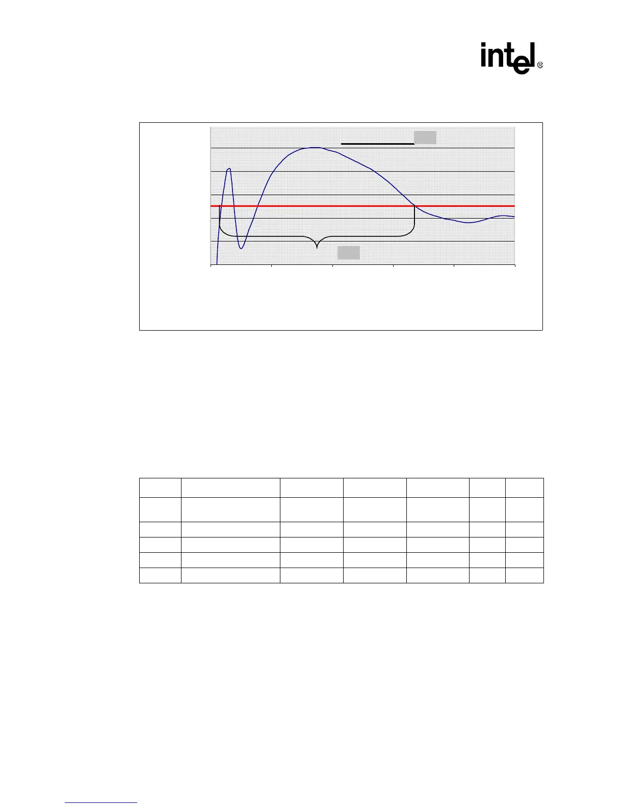
Figure 5. V
CC
Overshoot Example Waveform
0 5 10 15 20 25
Time [us]
Voltage [V]
VID - 0.000
VID + 0.050
V
OS
T
OS
T
OS
: Overshoot time above VID
V
OS
: Overshoot above VID
Table 12. BSEL[1:0] and VID[5:0] Signal Group DC Specifications
Symbol Parameter Min Typ Max Units Notes
1
R
ON
BSEL[1:0] and VID[5:0]
Buffer On Resistance
N/A 60 W 2
I
OL
Maximum Pin Current N/A 8 mA 2
I
LO
Output Leakage Current N/A 200 µA 2,3
R
PULL_UP
Pull-Up Resistor 500 W
V
TOL
Voltage Tolerance 0.95 * V
TT
V
TT
1.05 * V
TT
V