14
4.9. Activation and deactivation via pushbutton or key
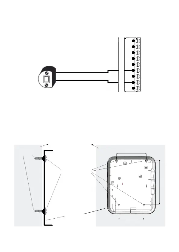
This product can be activated or deactivated through a retentive pushbutton or On/Off switch.
Connect the pushbutton or the switch to the Z1 and PGM terminal of the fence, as shown in the image below:
Buttonhole
LED+
LED-
COM
Z1
+
AUX
SIR+
-
PGM1
PGM2
CN1
Note: for Activation and deactivation via PGM or Activation and deactivation via pushbutton or
switch, the electric fence must be programmed to be activated/deactivated by the alarm sector.
According to the schedule in item 4.30. Arm/disarm the fence via the alarm sector.
4.10. Fixing the switch
The equipment must be xed to a xed wall or similar construction, so that the user cannot change its
position without the aid of tools. Always install the equipment in a vertical position and never upside
down or horizontally, check the diagram below.
Fixed wall or similar
construction
Screws of
nº 6 to 8
Gabinete
Side view
Front view
Plug
110
130
194,76