9
3. Products
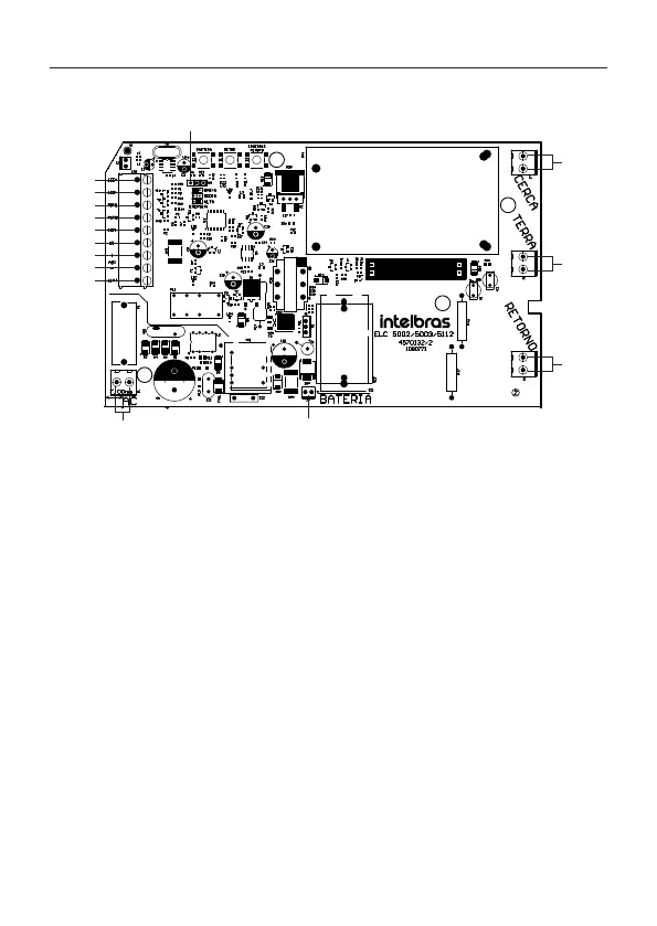
3.1. Main components
11 12
13
15
14
1
2
3
4
5
6
7
8
9
10
Internal view of the board
1. High voltage adjustment:
» With the Energy jumper in the low position = 8000 V pulsating (ELC 5112) or 16,000 V pulsating
(ELC 5002 / ELC 5003), ±5%.
» With the Power jumper in the middle position (disconnected) = 10,000 V pulsating (ELC 5112) or
18,000 V pulsating (ELC 5002 / ELC 5003), ±5%.
» With the Power jumper in the high position = 12,000 V pulsating (ELC 5112) or 20,000 V pulsating
(ELC 5002) or 21,000 V pulsating (ELC 5003), ±5%.
Note:
check model for correct output voltage.
2. Positive output for LED.
3. Negative output for LED.
4. Output PGM1.
5. PGM2 output.
6. Common for sensor connection.
7. Entry to zone 1.
8. Auxiliary output positive.
9. Auxiliary output negative and siren output.
10. Siren positive.
11. 115 – 230 Vac AC power supply.
12. Battery connector.
13. High voltage return.
14. Electrier Earth.
15. High voltage output.