16
4.12. Battery connection (bicolor parallel wire cable)
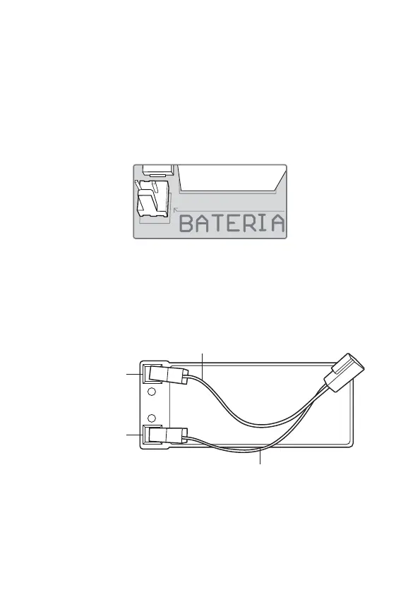
The J6 connector, as shown in the gure below, is used to connect the battery to the system. During
normal operation, this output acts as a battery charger and, in the event of a power failure from the
mains, it supplies energy to the system.
To install or replace the equipment’s battery, it is mandatory that the shock is deactivated by the remote
control, it is also necessary to turn off the electrical network through the safety switch or similar device.
Only after ensuring that the electric fence is completely inactive and without electricity, open the equip-
ment cover by loosening the screws and disconnect the J6 connector (battery). Then install and replace
the battery, closing and screwing the cover when nished.
It is necessary to obey the order indicated below, avoiding the risk of electric shock.
J 6
1. Disable shock by remote control;
2. Turn off the power supply using the safety switch or similar device;
3. Ensure the electric fence is completely inactive and free of electricity;
4. Open the equipment cover by loosening the screws and disconnect the J6 connector (battery);
5. Install and replace battery;
Battery snap orientation:
» Insert the battery cable;
Battery negative pole
Battery positive pole