CS750 User Manual
Rev E, April 2018
Page 18 of 31
Scoreboard
The output of the CS750 can be connected to a scoreboard to display continuous, real-
time information.
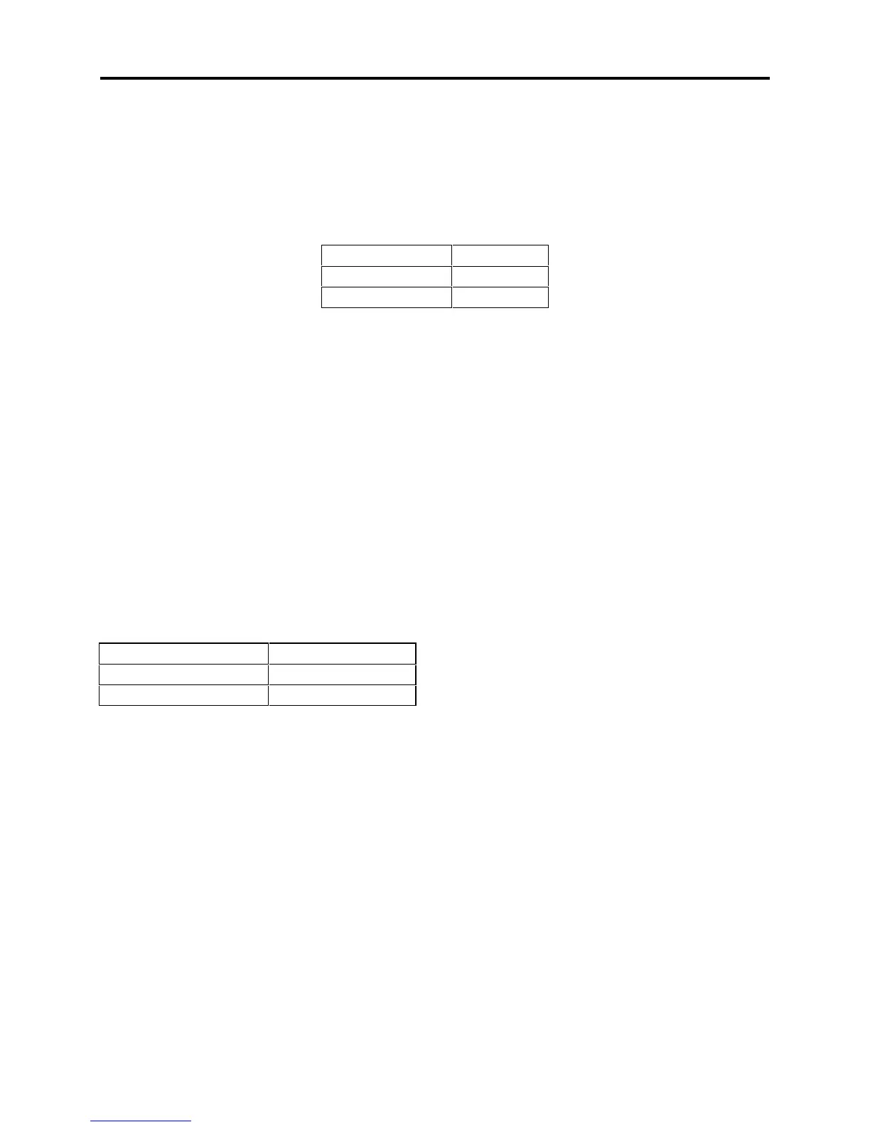
The signal is transmitted through the Serial I/O connector located on the side of the
unit. The connector has the following pinout:
The transmitted signal has the following characteristics:
Fixed 8 Data bits, no parity, 1 stop bit.
Baud rate is configurable with the "printer baud rate" setting in the "Mode Menu".
The output swings from -9 VDC to 9 VDC.
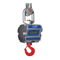
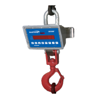
The scoreboard output is an externally available signal designed to drive a numeric
overhead display such as the Intercomp LED Display or a computer RS-232 input.
Continuous Print Mode Transmitted Data: xxxxxxx<cr><lf>
Transmitted data is displayed in either NET or GROSS weight, whichever is currently
shown on the Wireless CS750 display. Data is transmitted at a rate of once per a
second. However, the transmission may be delayed when motion is detected.
The xxxxxxx field will vary in size depending on the length of the number. The field may
also contain a decimal point and/or a minus sign.
The connection to a 9-pin PC communication port is referenced in the following table.