76 Installation Guide
Pin definitions
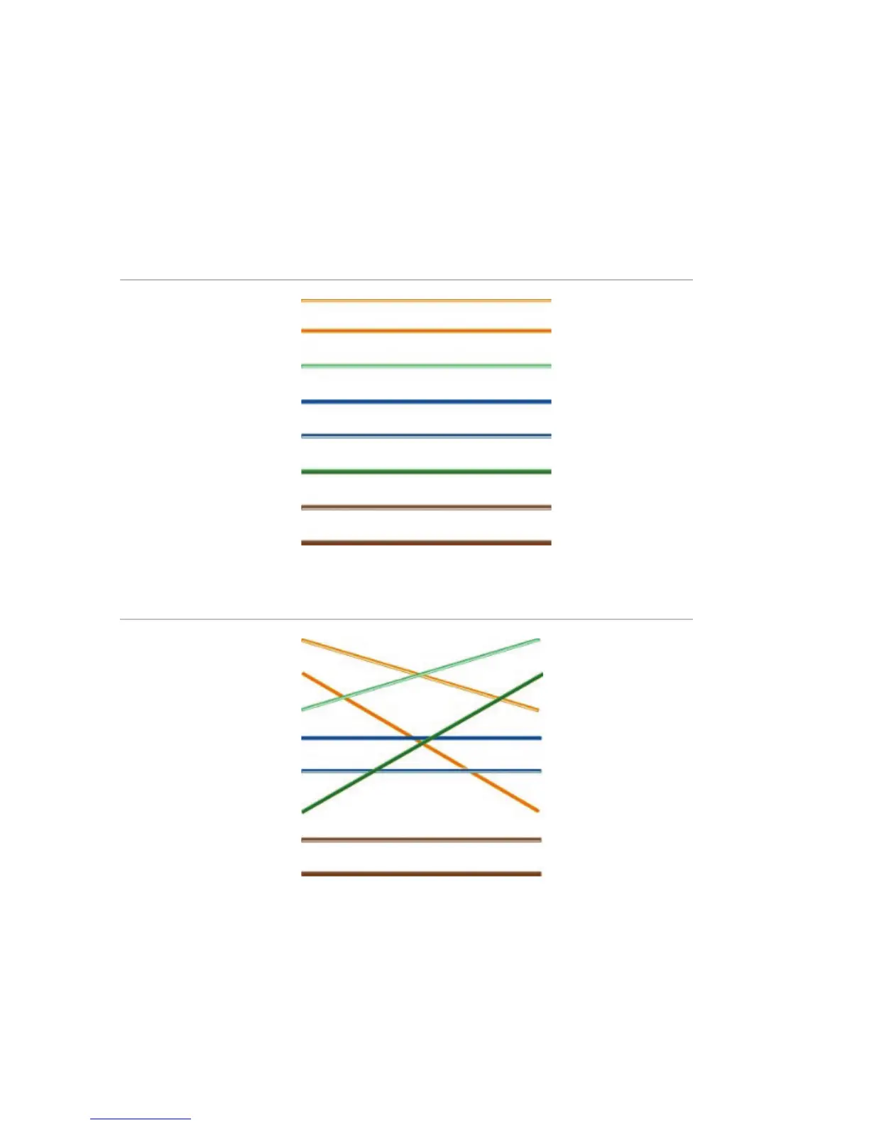
There are eight wires on a standard UTP/STP cable and each
wire is color-coded. The following shows the pin allocation and
color of straight and crossover cable connection:
Figure 9: Straight-through cable
1 White/Orange
White/Orange 1
2 Orange Orange 2
3 White-Green White-Green 3
4 Blue Blue 4
5 White/Blue White/Blue 5
6 Green Green 6
7 White/Brown White/Brown 7
8 Brown Brown 8
Figure 10: Cross-over cable
1 White/Orange
White/Orange 1
2 Orange Orange 2
3 White-Green White-Green 3
4 Blue Blue 4
5 White/Blue White/Blue 5
6 Green Green 6
7 White/Brown White/Brown 7
8 Brown Brown 8
Please make sure your connected cables have the same pin
assignment and color as above before deploying the cables in
your network.
 Loading...