40 Installation Guide
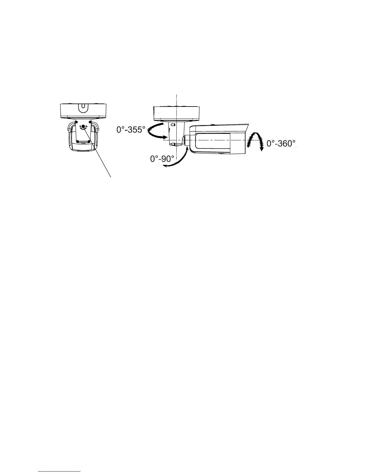
b) Adjust the view angle of the camera. The adjusting
range of the panning is from 0° to 360°, the tilting is
from 0° to 90° and the rotation is from 0° to 360°.
c) Tighten the lock screw.
Mounting the turret camera
To mount the fixed lens turret camera on a surface:
1. Place the drill template (supplied) on the surface where
the camera is to be mounted. Drill mounting holes in the
surface using the holes labeled number “1” on the drill
template.
To route the cable harness through the mounting surface,
cut a cable access hole in the mounting surface,
referencing the letter “A” on the drill template. Skip this
step if you want to route the cables on the surface.
 Loading...