www.intermatic.com
32
MultiWave Control System Installation Guide
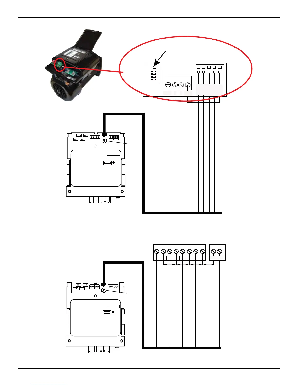
RS485
1 2 3
4 5
Step 1
Step 2
Step 3
OVRD
ICOM
ON
+12V A B
COM
Set Number 1
Dip Switch to
On Position
CAT5-568B Cable
Motor
Control
Input
White/Green, White/Orange, White/Blue, White/Brown
Orange
Green
Blue
Brown
Figure 4-12. Connecting the Century
®
Variable Speed Pump to the P5043ME.
Hayward EcoStar
®
Variable Speed Pump Connector
A B C D E F
G
H
PWR OUT
INPUTS
OUTPUTS
NP1 NP2 NP3 NP4 12/24 VAC
CAT5-568B Cable
Motor
Control
Input
White/Green, White/Orange, White/Blue, White/Brown
Orange
Green
Blue
Brown
Figure 4-13. Connecting the Hayward EcoStar
®
Variable Speed Pump to the P5043ME.