CK71 Service Work Instructions
The scan bracket assembly can now be serviced itself or set aside to be re-installed later. If the base scan bracket
assembly is being replaced you will remove the scan engine, camera, and side scan PCB’s and transfer them to the
replacement base scan bracket assembly. See the EA30 Scan Engine, EX25 Scan Engine, EV12 Scan Engine,
Camera, and Side Scan PCB operations elsewhere in this guide for tool, parts, & procedures related specifically to
those items.
Installation
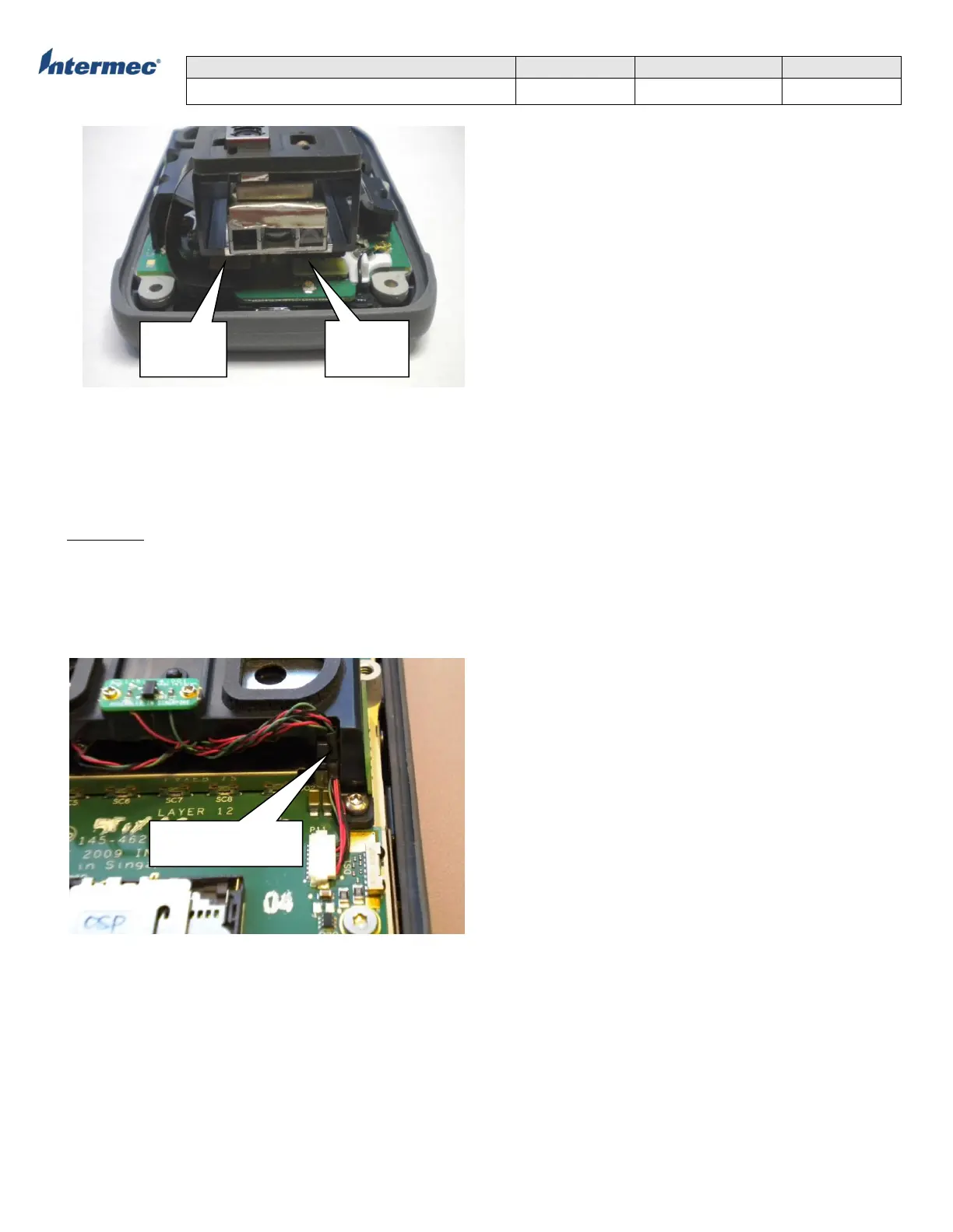
1. Position the scan bracket assembly over the main logic board and attach the scanner flex and camera flex cables..
2. Using a T7 torx driver install 4 screws and secure the scan bracket assembly to the core assembly with 2.5+/-0.2
in-lbs of torque.
3. Connect the scan switch/speaker cable to the main logic board. Make sure the cable is routed through the retention
feature in the bracket as shown below.
5. Re-install the bottom housing assembly.
Harness routed through
retention in bracket
cable
flex cable