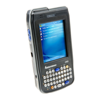
CK71 Service Work Instructions
The scan bracket assembly hosts the main unit speakers and scan handle sensor. It also provides the platform to
which the scan engine, camera, and side scan PCB’s are attached. Servicing this assembly will generally require that
it be removed from the CK71A. It will also need to be removed and then re-installed when servicing other assemblies
such as the main logic board.
Any failure of the bracket itself, the speakers, the speaker gaskets, the scan handle sensor, or the harness that
connects the speakers and sensor to the main logic board will require that the base scan bracket assembly be replaced.
The base scan bracket assembly contains these items already factory installed. For the CK71A there are different
scan bracket assemblies, one for each different scan engine option. The scan engine, camera, and side scan PCB’s
can be individually replaced. Refer to other operations in this guide related specifically to those items.
Tools Required
Parts Required
EA30 SCAN BRACKET CK71, SPARE
EX25 SCAN BRACKET CK71, SPARE
EV12 SCAN BRACKET CK71, SPARE
N5603 SCAN BRACKET CK71, SPARE
SCREW 2-56X0.1875 PH TORX W/NYL CRES ROHS
Removal
1. Remove the bottom housing assembly (refer to Bottom Housing operation).
2. Disconnect the scan switch/speaker harness from the main logic board.
3. Using a T7 torx driver remove 4 screws that secure the scan bracket to the core assembly.
4. Gently lift the scan bracket away from the core assembly.
5. Disconnect the scan engine and camera flex cables from the main logic board.
Scan switch/speaker
harness connector