11
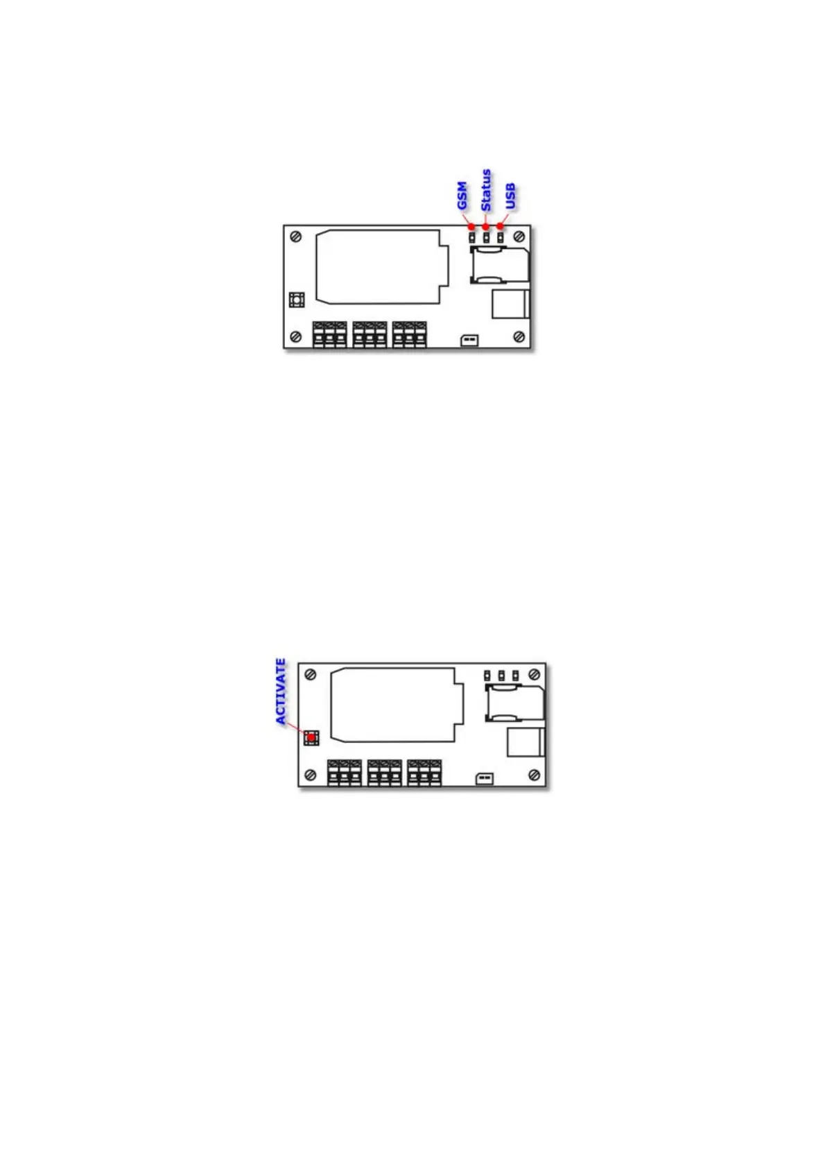
3.6. LEDs
The LEDs placed on the MT-703 module board simplify the running process of the
module.
The LEDs have strictly assigned meanings:
The GSM LED indicates the operation mode of the GSM module.
The Status LED indicates activity and stand-by states of the GSM module.
The USB LED indicates powering the module from external computer.
The detail description of signaling functions of the LEDs is given in the chapter LED
signaling.
3.7. ACTIVATE button
The ACTIVATE button placed on the module board enables the immediate switching
the module from stand-by to active state. If the module is active, the button switches it
to the stand-by mode with 10 seconds delay after pushing.
Such capability is useful when you want to check the GSM signal level and the module
is in a stand-by mode. After pushing the ACTIVATE button, the module is waken up
for 2 minutes and logins onto GSM network and onto GPRS. During this operations you
can see the current GSM signal level indicated by the STATUS LED.
If the module is in the active mode, pushing the ACTIVATE button causes changing its
status to stand-by for at least 2 minutes. It may cause the loss of events triggered by
T1 or T2 timers, but assures the safe battery replacement.
3.8. RESET button
The RESET button is placed on the bottom side of the module board. It ensures the
hardware reset of the module.

 Loading...