13
4. Connecting the module
In this chapter we present the recommended configurations for connecting the MT-703
module, providing proper operation of its integrated inputs. There are configurations
used for connecting the module:
Binary inputs I1, I2
Analog inputs AN1, AN2
Supply voltage
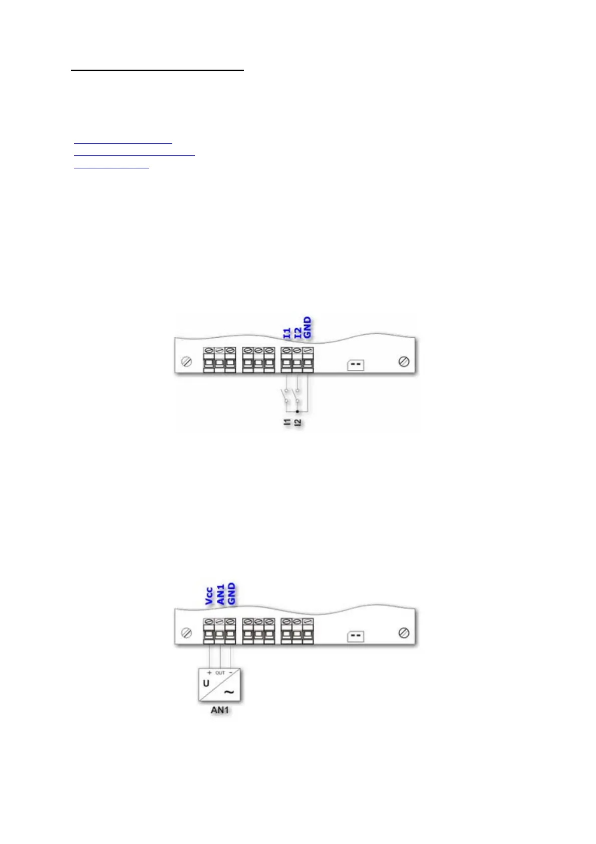
4.1. Connecting the binary inputs I1, I2
Due to the permanent activity of the binary inputs as well as the energy-saving
operation of the MT-703 module, the binary inputs require a connection with potential-
free contacts only. Such contacts are placed between the input and the module ground
connectors. Closing the contact is treated as a high state on the input (the negative
logic).
As you can see on the above picture, both inputs have the same reference potential.
This is the electrical mass of the module, i.e., the negative pole of the supply voltage.
The potential on the opened binary inputs is not greater than 2.5 VDC.
4.2. Connecting the analog inputs A1, A2
The analog inputs of the MT-703 module are the voltage type, with the input voltage
range from 0 to 3.3 VDC.

 Loading...