DA180 series basic AC servo drive Function codes
-134-
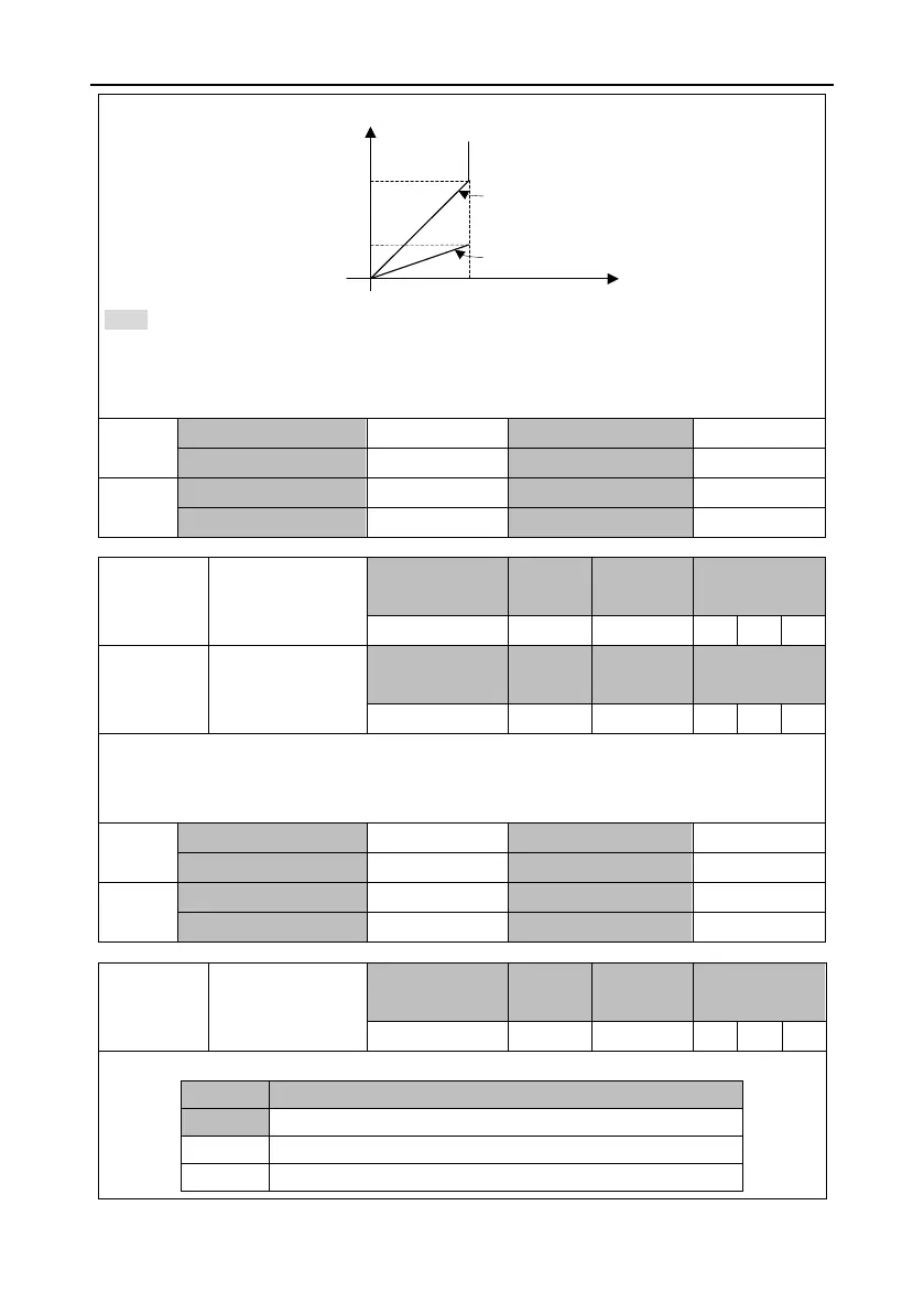
the following figure for the relationship between the actual speed reference and output voltage:
10.00V
3000r/min
AO1 output voltage (V)
Speed (r/min)
P3.31=300
P3.31=100
1000r/min
Note:
In the example, when the actual output speed is 3000 r/min or above, the output voltage of AO1
is always 10V. Select proper gain according to the actual situation.
If other functions are set for P3.30 and P3.32, the gain setting method is similar.
This group of parameter is used to adjust voltage of analog output 1 and analog output 2.
Actual value of analog output voltage = Original value of analog output voltage + Offset value of
analog output voltage
This parameter specifies the output mode and voltage range of analog output (AO).
Voltage output with signs (-10V–10V)
Absolute voltage output (0V–10V)
Zero-bias voltage output (0V–10V, 5V as the bias center)
 Loading...
