EasyManuals Logo

INVT DA180-S5R0SG0 User Manual

INVT DA180-S5R0SG0
316 pages
To Next Page IconTo Next Page
To Previous Page IconTo Previous Page
Page #32 background imageLoading...
Page #32 background image
DA180 series basic AC servo drive Wiring instructions
-26-
Wiring mapping
Signal
X1
X2
Core wire
color
GND
X1.12
X2.4
VB-3.6V
/
X2.5
Twisted pair
VB-GND
/
X2.6
PE
Metal
shell
Metal shell
Woven
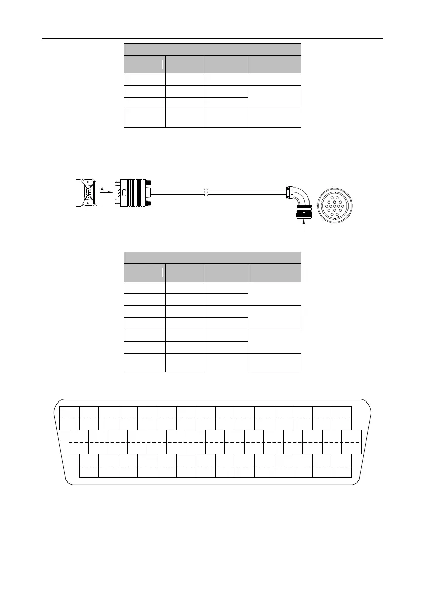
3.4.2 Cable for 17- or 23-bit encoder used by base-130 motors
1
11
15
5
6
10
X1
12
3
5
610
11
13
1415
X2
B
Vi ew i n d i r ec ti on A
Vi ew i n d i r ec ti on B
Wiring mapping
Signal
X1
X2
Core wire
color
SD+
X1.1
X2.1
Twisted pair
SD-
X1.7
X2.2
5V
X1.5
X2.3
Twisted pair
GND
X1.12
X2.4
VB-3.6V
/
X2.5
Twisted pair
VB-GND
/
X2.6
PE
Metal
shell
Metal shell
Woven
3.5 Wiring for control I/O terminal CN1
24
PULS-
23
PULS+
CN1 plug pin and signal layout
44
OA+
43
OA-
42
OB-
41
OB+
40
12V
39
DI4
38
OCP
37
DI2
36
-
35
DO4-
34
DI5
33
SIGN-
32
SIGN+
31
OCS
30
-
29
DO4+
28
OZ+
27
OZ-
26
-
25
-
22
DI10
21
-
20
AD1
19
DO2-
18
DI9
17
DI6
15
DO2+
14
DO1+
13
-
12
GND
11
DO3+
10
DI3
9
-
8
DO3-
7
AD2
6
GND
5
DO1-
4
DI8
3
DI7
2
COM+
16
DI1
1
-
Note: For details about the terminal functions and applications, see chapter 4 "Control modes".

Table of Contents

Questions and Answers:

Question and Answer IconNeed help?

Do you have a question about the INVT DA180-S5R0SG0 and is the answer not in the manual?

INVT DA180-S5R0SG0 Specifications

General IconGeneral
ModelDA180-S5R0SG0
Output Current5.0A
Protection LevelIP20
Rated Current5.0 A
Communication InterfaceRS485
Rated Power1.8kW
Feedback TypeIncremental Encoder
Protection FeaturesOvercurrent, overvoltage, undervoltage, overheat

Related product manuals