Goodrive350 series high-performance multi-function inverter Chapter 6
-120-
cancelled by setting P07.00 to 0; if P01.00 is set to a non-zero value, the parameter will be protected
by password. When modifying function parameters through serial communication, the function of user
password also follows above rules.
Detailed parameter description
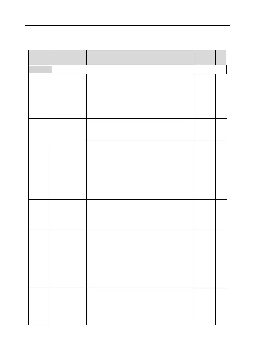
P00 group Basic functions
0:SVC 0
1:SVC 1
2:SVPWM
3:VC
Note: If 0, 1 or 3 is selected, it is required to carry out
motor parameter autotuning first.
0: Keypad
1: Terminal
2: Communication
Communication
running
command
channel
0:MODBUS
1:PROFIBUS/CANopen/Devicenet
2:Ethernet
3:EtherCat/Profinet
4:PLC programmable card
5:Bluetooth card
Note: 1, 2, 3, 4 and 5 are extended functions which
are applicable with corresponding cards.
Used to set the max. output frequency of the inverter.
It is the basis of frequency setup and the
acceleration/deceleration.
Setting range: Max (P00.04, 10.00) –630.00Hz
Upper limit of
running
frequency
The upper limit of running frequency is upper limit
value of inverter output frequency. This value should
be no more than the max. output frequency.
When the set frequency is higher than the upper limit
frequency, the inverter runs at the upper limit
frequency.
Setting range: P00.05–P00.03 (max. output
frequency)
Lower limit of
running
frequency
The lower limit of running frequency is the lower limit
value of inverter output frequency.
When the set frequency is lower than the lower limit
frequency, the inverter runs at the lower limit
frequency.

 Loading...
